Time to read: 21 min
CNC Milling vs. CNC Turning: Which Process Is Suitable for Your Part?
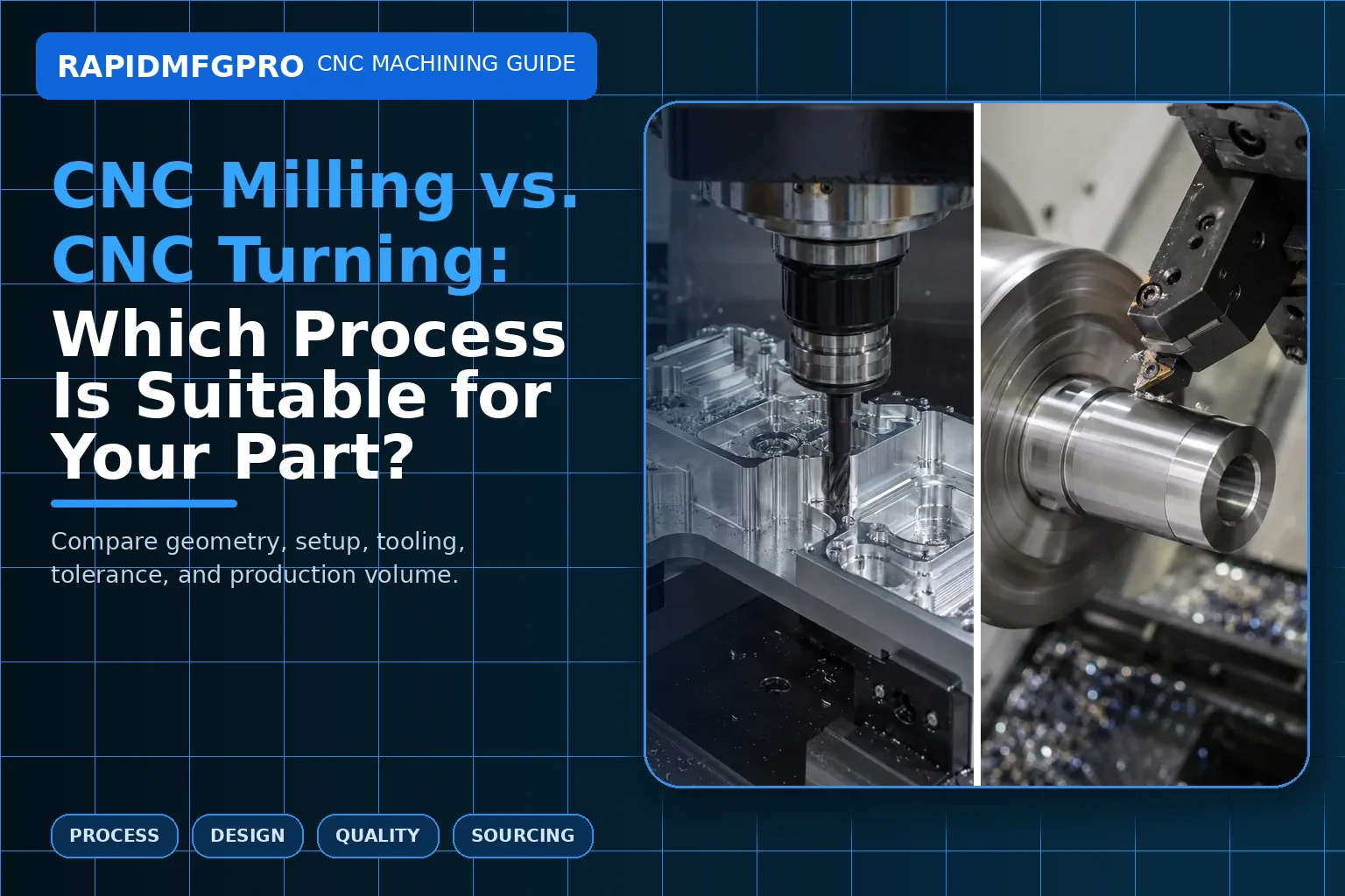
Direct answer: Choose CNC milling when the part is mainly prismatic and needs flat faces, pockets, slots, hole patterns, or multi-sided features. Choose CNC turning when the part is mainly rotational and needs concentric diameters, shoulders, grooves, bores, or threads. Use both processes when a turned body also needs flats, cross holes, slots, or off-axis features. The suitable route is the one that creates the critical features in the fewest stable setups—not simply the one associated with the part’s overall appearance.
CNC milling and CNC turning are often presented as competing processes, but in practice they are complementary. A supplier may turn a cylindrical blank and mill secondary features, or mill a housing and bore a precision diameter. The decision affects fixture count, tolerance transfer, machine time, material use, and supplier selection. This guide provides a detailed comparison and explains how RapidMfgPro can help buyers match a part to independent suppliers with the correct process combination.
What Is the Core Difference between CNC Milling and CNC Turning?
Milling rotates the cutting tool
In CNC milling, the workpiece is normally clamped while a rotating cutter moves along controlled axes. End mills, face mills, drills, reamers, and special tools create flat surfaces, pockets, slots, holes, contours, and complex multi-face geometry.
Milling is commonly used for brackets, plates, bases, housings, manifolds, molds, fixtures, heat sinks, robot links, optical mounts, and other parts that are not dominated by a single rotational axis. Three-axis machines handle accessible top-side features, while four-axis and five-axis machines reach additional faces or angles.
Turning rotates the workpiece
In CNC turning, the workpiece rotates in a chuck or collet while cutting tools move relative to it. This naturally creates cylindrical, conical, threaded, and grooved surfaces around the spindle axis.
Turning is commonly used for shafts, pins, bushings, rollers, nozzles, spacers, rings, flanges, threaded fittings, and components with multiple concentric diameters. Live-tool turning centers can also add milled features.
| Comparison point | CNC milling | CNC turning | Practical implication |
|---|---|---|---|
| Main rotation | Cutting tool rotates | Workpiece rotates | Determines which geometry is produced most naturally |
| Typical geometry | Prismatic, multi-face, pocketed | Cylindrical, concentric, axial | Start by identifying dominant functional features |
| Common workholding | Vise, fixture plate, soft jaws, vacuum | Chuck, collet, centers, mandrel | Gripping strategy affects marks and repeatability |
| Common axes | 3, 4, or 5 axes | X/Z plus optional C/Y and live tooling | Machine capability affects number of setups |
| Best strength | Faces, pockets, hole patterns, complex surfaces | Diameters, bores, grooves, threads, runout control | Use each process for its natural geometry |
How Does Part Geometry Guide the Decision?
Identify the dominant manufacturing axis
A turned part usually has most functional surfaces arranged around one centerline. A shaft with three diameters, two bearing journals, a shoulder, and an external thread is a clear turning candidate. Even if it also has one cross hole, turning remains the primary process.
A milled part usually has functional relationships among several planes or coordinate directions. A gearbox housing with mounting faces, pockets, a bolt pattern, and a bearing bore is primarily a milling candidate, even though the bore is circular.
Do not judge only by the outer silhouette. A round plate with many off-axis pockets may be better on a mill. A rectangular blank that becomes a cylindrical pin may be wasteful compared with round bar and turning.
Look at tool access and feature relationships
Milling tools need access from a direction. Turning tools need radial or axial access to the rotating workpiece. Deep internal bores favor turning or boring, while broad pockets and flat sealing faces favor milling. Undercuts may need special tools in either process.
The most important features should be made in the same setup when possible. If two bearing diameters must be concentric, turning them together is logical. If a bore must be precisely located relative to a mounting face and dowel pattern, milling and boring in one setup may be preferable.
Which Features Favor Milling or Turning?
Flat and multi-sided features favor milling
Large flat faces, rectangular pockets, ribs, bosses, engraved channels, slot patterns, and complex surface contours are generally easier to create by milling. Four-axis and five-axis machines can produce features on several sides without repeated manual repositioning.
Milling also supports precise hole patterns referenced to planar datums. This is important for enclosures, brackets, fixtures, manifolds, and machine frames. If the part must align several components in a coordinate system, milling is often the primary process.
Concentric and axial features favor turning
Outside diameters, inside diameters, grooves, tapers, threads, and shoulders are efficient on a lathe. Because the part rotates around the spindle, turned surfaces can maintain strong concentric relationships.
Long shafts and small pins may require centers or Swiss-type support. Large rings and hubs may use vertical turning. The turning machine type should match diameter, length, rigidity, and quantity.
| Feature or part type | Usually preferred | Reason | Possible hybrid route |
|---|---|---|---|
| Rectangular electronics housing | Milling | Pockets, covers, connector openings, flat datums | Turn only a separate threaded insert |
| Stepped motor shaft | Turning | Concentric diameters and shoulders | Mill keyway or flats after turning |
| Flanged bushing with bolt circle | Turning first | Main bore and flange share an axis | Live-tool or second-operation drilling |
| Hydraulic manifold block | Milling | Multi-face drilled passages and ports | Turn threaded cartridge components separately |
| Robot joint housing | Milling | Bearing bores related to faces and motor mounts | Turn an inner ring or shaft |
| Camera lens barrel | Turning | Optical axis, threads, internal diameters | Mill mounting flats or connector features |
How Do Milling and Turning Compare for Tolerances?
Turning naturally controls diameters and runout
When several diameters are cut in one turning setup, the spindle axis provides a common reference. This is useful for bearing journals, seal diameters, and threaded interfaces. Runout can still be affected by chucking, stock, tool pressure, and second operations, but the process is naturally aligned with rotational tolerances.
Very tight roundness, cylindricity, or surface finish may require grinding or honing after turning. A drawing should distinguish size tolerance from form and runout.
Milling controls planar and positional relationships
Milling is effective for flatness, perpendicular faces, hole position, profile, and relationships among multiple datums. A stable fixture and one-clamping strategy can keep faces and holes aligned. Machine probing may improve location and verification.
A large thin milled plate can move after unclamping even if the machine follows the program perfectly. Material stress and support matter. Therefore, tolerance capability must be evaluated on the actual part geometry, not only the machine specification.
How Do Surface Finish and Appearance Differ?
Turning produces a helical feed pattern
A turned surface typically shows circular or helical tool marks. Feed rate, insert nose radius, tool condition, material, and vibration affect roughness. For seal surfaces, spiral lead may matter even when the measured Ra is acceptable.
Facing creates circular patterns on end surfaces. A cosmetic turned part may need polishing, bead blasting, or another finish. These processes should not remove critical edges or alter fits.
Milling produces directional or scalloped tool marks
Face milling creates arcs or hatch patterns. Side milling creates linear feed marks. Ball-nose finishing creates scallops on contoured surfaces. The direction and visibility of marks depend on toolpath strategy and lighting.
If appearance matters, the drawing should identify cosmetic faces, acceptable tool marks, and finishing method. “Smooth” is not a measurable requirement. Define roughness where functional and use visual standards where cosmetic.
| Requirement | Milling consideration | Turning consideration | Recommended specification |
|---|---|---|---|
| Bearing fit | Bore by interpolation, boring head, reaming | Turn or bore in spindle setup | Size, fit, form, roughness, datum |
| Flat sealing face | Face mill or grind | Face turn or grind | Flatness, roughness, scratch limit |
| Concentric seal diameter | Possible with rotary setup or boring | Natural turning feature | Runout relative to datum axis |
| Hole pattern | Natural coordinate feature | Requires live tooling or second setup | Position tolerance relative to datums |
| Cosmetic surface | Directional marks or blast finish | Circular/helical marks or polish | Visual sample, gloss, color, protected faces |
How Do Material and Stock Form Affect the Choice?
Start from a stock shape close to the finished geometry
Round bar or tube is efficient for turned parts. Plate and rectangular bar are efficient for milled parts. Choosing the wrong stock form creates unnecessary material removal. A large ring cut from solid plate may waste material compared with forged ring stock. A rectangular bracket cut from round bar would be inefficient.
Availability matters. A rare alloy may be available only in certain diameters or plate thicknesses. The supplier may recommend a different stock form or a near-net-shape blank.
Material behavior affects both processes differently
Long chips can interfere with turning. Deep pockets can trap chips during milling. Titanium retains heat near the cutting edge in both processes. Plastics can deform from chuck pressure in turning or from clamping and heat in milling.
Thin-wall aluminum housings may distort during milling. Thin rings may become oval after turning. The correct process plan balances stock removal, clamping, and stress relief.
How Do Cost, Quantity, and Lead Time Compare?
Turning is often faster for rotational parts
A lathe can remove material continuously around a diameter. Bar feeders, sub-spindles, and automatic part catchers support efficient repeated production. For a simple shaft or bushing, turning usually has lower cycle time than milling the same shape.
However, complex off-axis features can reduce this advantage. If live tooling is slow or limited, a separate milling operation may be more economical. The supplier should compare total route time.
Milling cost depends heavily on setup count and material removal
A milled part with accessible features on one or two sides may be economical. A part needing six manual orientations, deep roughing, and long 3D finishing will cost more. Five-axis machining may reduce handling but uses higher-cost equipment and programming.
Quantity changes the fixture strategy for both processes. Dedicated soft jaws, collets, fixtures, bar feeds, or pallet systems become worthwhile as volume increases. Ask for quantity breaks and separate tooling charges.
| Cost driver | Milling impact | Turning impact | Buyer action |
|---|---|---|---|
| Number of setups | Multiple faces may require fixtures | Second end or off-axis features add setups | Ask for proposed process route |
| Material removal | Deep pockets and large billet reduction add time | Large diameter reduction adds time | Consider near-net stock |
| Special features | Undercuts and 3D surfaces require tools | Deep grooves, long bores, special threads require tools | Use standards where practical |
| Volume | Fixtures and pallets improve repeatability | Bar feeding and collets improve automation | Provide prototype and annual demand |
| Inspection | CMM may be needed for multi-datum geometry | Gauges and runout checks may dominate | Define critical dimensions and report scope |
When Should a Part Use Both Milling and Turning?
Mill-turn parts combine a rotational body with off-axis features
Examples include a shaft with wrench flats, a bushing with a bolt circle, a nozzle with side ports, a lens barrel with mounting tabs, and a flanged connector with cross holes. These can be completed on a turning center with live tooling or transferred between a lathe and mill.
One-machine completion can reduce handling and datum-transfer error. It may also simplify scheduling. However, live tooling may be less powerful than a dedicated machining center, so heavy pockets or large flat faces may still be faster on a mill.
Process sequence should protect critical datums
If the turned diameter is the primary datum, the milling fixture should locate from that diameter or a related face. If the milled face controls the assembly, the process may establish that face first. The drawing’s datum structure should guide the route.
Buyers should ask whether critical features are completed before or after heat treatment and coating. The sequence can change final size and runout.
How Can You Decide Which Process Fits Your Part?
Use a feature-based decision sequence
- Identify the surfaces that control function, assembly, sealing, rotation, or alignment.
- Determine whether those surfaces are mainly concentric around one axis or related to multiple planes.
- Check whether all features are accessible in a stable setup.
- Review stock form, material, quantity, tolerance, finish, and secondary operations.
- Compare a single-process route with a hybrid route.
Do not choose from the part name alone. A “housing” may be turned if it is a cylindrical optical barrel. A “shaft support” may be milled if it is a rectangular bearing block.
Ask the supplier to explain the proposed route
A reliable quotation should identify the primary machine type, number of setups, outside processes, and inspection scope. The lowest price may assume loose tolerances, omit finishing, or use a process that creates avoidable risk.
For uncertain designs, a DFM discussion can reveal whether a small geometry change would allow one-machine completion, standard stock, or simpler fixturing.
How Does RapidMfgPro Support Milling-versus-Turning Sourcing?
Submit the geometry and the business context
Provide the STEP model, drawing, material, quantity, finish, target date, inspection requirements, and expected repeat volume. Mention whether design changes are possible. A supplier recommendation should account for both technical fit and production context.
RapidMfgPro can review the project and identify independent suppliers with suitable milling, turning, or mill-turn capability. Machine envelope, chuck size, spindle bore, axis count, live tooling, fixture experience, metrology, and material history all influence the match.
Compare complete process routes
RapidMfgPro’s role is to support the search and comparison, not to claim that every part is made in one owned factory. Buyers should evaluate the proposed route, quality documents, lead time, secondary processing, commercial terms, and supplier qualification.
A well-matched supplier should be able to explain why milling, turning, or a hybrid route is appropriate. That explanation is often more valuable than a generic machine list.
What Are Borderline Parts That Need a Closer Process Review?
Round parts with dominant milled features
A circular plate may seem like a turning part, but if most work consists of pockets, bolt patterns, channels, and rectangular openings, milling may be the primary process. The outer diameter can be milled by circular interpolation or turned first from round stock. The best choice depends on diameter tolerance, stock availability, and the amount of off-axis work.
A wheel hub is another borderline case. The bearing bore, seal diameters, and flange faces favor turning, while bolt patterns and sensor features favor milling. A mill-turn center may complete the part efficiently, but a two-machine route can be more economical if production volume is low or milling features are heavy.
Rectangular parts with critical rotational interfaces
A bearing block is rectangular but contains a bore whose axis and roundness are critical. It is usually milled and bored in one setup. Turning the bore separately is not practical because the outer geometry does not provide a rotational blank. The supplier may use a precision boring head or interpolation followed by reaming or honing.
A gearbox housing can include several bores that must align. A horizontal machining center or line-boring strategy may be more important than the simple milling-versus-turning label. The critical question is how the axes are created and inspected relative to mounting datums.
What Sourcing Mistakes Occur When Choosing between Milling and Turning?
Choosing by machine hourly rate instead of total route
A low hourly rate can be misleading if the part requires many setups, manual transfers, and outside operations. A higher-rate 5-axis or mill-turn machine may complete the part with fewer fixtures and lower total risk. Buyers should compare total quoted cost, first-article effort, inspection, and repeatability.
Ask each supplier to describe the main operation sequence. The explanation does not need to disclose proprietary toolpaths, but it should show whether the supplier understands the critical features and datum flow.
Ignoring future volume and design evolution
A prototype route may use flexible standard fixtures. A recurring batch may justify soft jaws, bar feeding, tombstone fixtures, or automated inspection. If volume is likely to increase, ask whether the proposed supplier can scale or whether the process will need to move later.
Design maturity also matters. A mill-turn route may reduce handling, but it can require more programming before the design is stable. For frequently changing prototypes, separate simple operations may be more flexible. RapidMfgPro can use expected volume and revision frequency when identifying supplier options.
How Can a Simple Decision Matrix Support Process Selection?
Score the part by functional feature groups
List every critical feature and assign it to a process family: concentric turning features, planar milling features, precision holes, secondary finishing, and inspection. Then score the importance of each group. If rotational features dominate both quantity and tolerance, turning should lead. If multi-face relationships dominate, milling should lead.
Next, evaluate setup count. A process that appears secondary may become primary if it can hold several important features in one clamping. Include stock form and material-removal volume because these strongly affect cost.
Use the matrix to compare supplier proposals
Two suppliers may propose different routes. One may use a live-tool turning center; another may use a lathe and machining center. Compare fixture count, datum transfer, cycle time, inspection, tooling, and scalability. Both routes may be valid, but they carry different risks.
The decision matrix creates a documented basis for selection. It also helps the buyer explain why the lowest quote was not chosen when a different route offers better tolerance control or repeat-production stability.
How Does Inspection Strategy Influence the Process Choice?
Choose a process that makes the critical feature measurable
A process route should not create a feature that cannot be inspected economically. Turned diameters can often be measured with micrometers, bore gauges, air gauges, or runout fixtures. Milled positional relationships may require a CMM, height gauge, optical system, or functional fixture. When a part uses both processes, the inspection plan should follow the datum transfer between them.
For example, a flanged shaft with a milled bolt pattern may be turned first and then located from the finished bore during milling. The final CMM report should verify the bolt pattern relative to the turned datum axis, not only to the milling fixture.
Use functional gauges when they reduce ambiguity
A functional gauge can verify whether several holes, pins, or interfaces assemble under worst-case conditions. This can be more meaningful than inspecting every coordinate separately. Rotational assemblies may use master rings, plug gauges, or mating fixtures to verify fit and runout.
The supplier proposal should explain which characteristics are checked on the machine, in the inspection room, or with a functional gauge. RapidMfgPro can use this information when comparing process routes because a theoretically capable machine is not enough if the final requirement cannot be verified.
Conclusion
CNC milling is normally best for prismatic, multi-face parts; CNC turning is normally best for rotational parts with concentric features. Many real components require both. The correct decision comes from the critical geometry, datum relationships, workholding, material, quantity, finish, and inspection—not from the part’s name or appearance. RapidMfgPro can help buyers submit a structured project package and identify independent suppliers with suitable milling, turning, or mill-turn capability for further technical and commercial evaluation.
Need Help Reviewing a Custom Part?
Share your CAD file and requirements to request supplier matching. Supplier capability and commercial terms must be verified before order placement.
Request Supplier Match