Time to read: 8 min
How Do You Design Holes, Threads, and Tapped Features for CNC Machining?
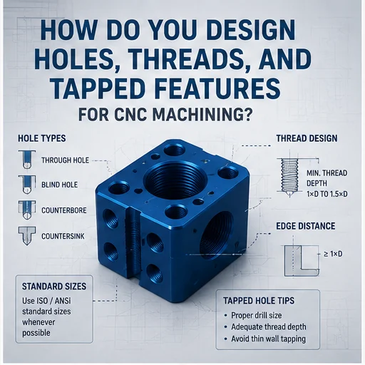
Thin-wall CNC parts are common in aerospace housings, robotic arms, optical frames, medical equipment, electronics enclosures, automotive structures, battery components, fluid manifolds, and lightweight mechanical assemblies. They reduce weight and material use, but they also create one of the most difficult machining problems: the wall can bend during cutting, move under clamping force, distort after material removal, or change shape after heat treatment and surface finishing.
A thin wall that looks acceptable in the CAD model may behave very differently during manufacturing. Cutting force, residual stress, temperature, unsupported span, tool engagement, material condition, clamping pressure, and machining sequence all affect the final shape. For this reason, thin-wall design cannot be separated from the manufacturing plan.
Reducing deformation does not mean making every wall thick. The objective is to use the minimum practical wall thickness while preserving stiffness, dimensional stability, tool access, inspection access, assembly function, and production repeatability. Ribs, fillets, local bosses, balanced geometry, staged machining, stress relief, soft fixturing, and realistic tolerance zones can all reduce risk.
RapidMFGPro evaluates thin-wall projects from a supplier-matching perspective. The review considers the material, wall thickness, unsupported span, machining direction, clamping method, quantity, tolerance, heat treatment, surface treatment, inspection, and packaging before identifying suppliers with suitable 3-axis, 4-axis, 5-axis, turning, thin-wall fixturing, stress-relief, and metrology capabilities.
This guide explains how thin-wall deformation occurs and how engineers, designers, and buyers can reduce it before the part reaches production.
Why Do Thin-Wall CNC Parts Deform?
Thin-wall deformation usually comes from a combination of cutting force, clamping force, residual stress, heat, geometry, and process sequence. The final error may appear during machining or only after the part is released.
Low Structural Stiffness
Thin walls bend more easily than thick sections because their resistance to deflection is low.
A small increase in wall height or unsupported span can create a large increase in movement.
Cutting Force
The cutting tool pushes the wall while removing material. If the wall moves away from the tool, the actual cut becomes shallower than programmed.
When the wall springs back, the dimension can be oversized or tapered.
Clamping Force
Vises, jaws, clamps, vacuum fixtures, and bolts can distort the part before machining begins.
The part may appear correct while clamped and change shape after release.
Residual Stress
Rolled plate, extrusion, forging, casting, heat treatment, and previous machining can leave internal stress.
Removing material from one side releases the stress unevenly and causes warping.
| Cause | Typical Symptom | Design or Process Response |
|---|---|---|
| Cutting force | Wall taper or local bending | Shorter span, sharper tools, lighter engagement |
| Clamping force | Part changes after unclamping | Broad support and lower clamping pressure |
| Residual stress | Global warping after roughing | Balanced machining and stress relief |
| Machining heat | Temporary expansion or permanent movement | Heat control and cooling pauses |
| Unsupported geometry | Chatter and vibration | Ribs, local thickness, and temporary support |
What Counts as a Thin-Wall Part?
There is no single universal wall thickness that defines a thin-wall CNC part. The practical definition depends on material stiffness, wall height, wall length, geometry, tolerance, and machining direction.
Thickness-to-Height Relationship
A 1 mm wall may be stable when only 5 mm high but highly flexible when 80 mm high.
Wall slenderness is more useful than thickness alone.
Unsupported Span
A long free edge deforms more than a wall connected to ribs or neighboring faces.
Support spacing should be reviewed across the full geometry.
Material Influence
Steel, aluminum, titanium, magnesium, copper, and plastic walls of the same dimensions have different stiffness.
Material modulus, not only strength, affects deflection.
Tolerance Influence
A wall may be manufacturable for a ±0.20 mm tolerance but impractical for ±0.02 mm.
Thin-wall classification should therefore include the tolerance requirement.
Start with the Functional Load Path
A thin-wall design should begin with how force travels through the part in service. Material should remain where it contributes to stiffness and be removed where it contributes little.
Identify Primary Loads
Determine whether the part experiences bending, torsion, compression, vibration, impact, pressure, or assembly preload.
Thin walls aligned with the load path perform better than unsupported decorative surfaces.
Keep Material near Structural Boundaries
Flanges, corners, closed sections, ribs, and perimeter walls increase stiffness efficiently.
A deep closed housing can be stiffer than a thicker flat plate using the same material mass.
Avoid Isolated Flexible Panels
Large flat panels with no rib or perimeter support are vulnerable to machining and service deformation.
Breaking the span into smaller sections improves stability.
How Should Wall Thickness Be Selected?
Wall thickness should be selected from material stiffness, unsupported height, tolerance, cutting access, surface finish, and production quantity rather than copied from a general minimum guideline.
Use a Practical Starting Thickness
Early concepts should use a conservative wall thickness and reduce it only after stiffness and manufacturing review.
Very thin values should be justified by weight, packaging, thermal, or assembly requirements.
Separate Functional and Cosmetic Walls
Functional walls that locate components or seal fluid need more stability than cosmetic covers.
Different wall zones may use different thicknesses.
Consider Quantity
A prototype can tolerate longer machining time, temporary supports, and manual straightening.
Production parts need a stable process with predictable cycle time and low reject rate.
Consider Final Finish
Grinding, anodizing, plating, heat treatment, bead blasting, and polishing can change wall thickness or stress.
The machined thickness should account for all subsequent operations.
Why Is Uniform Wall Thickness Important?
Uniform wall thickness promotes balanced cutting, thermal behavior, residual-stress release, and surface finishing.
Balanced Material Removal
Similar wall sections can be rough-machined using a repeatable sequence.
Abrupt changes in thickness release stress unevenly.
Reduced Thermal Gradients
Thin sections heat and cool faster than thick bosses.
Uniform thickness reduces local expansion during machining and heat treatment.
Improved Surface Treatment
Uniform sections respond more consistently to anodizing, plating, coating, and chemical cleaning.
Thick-to-thin transitions may show color or dimensional differences.
When Should Local Thickness Be Added?
Uniform thickness is useful, but local reinforcement is appropriate where the wall carries load, holds threads, supports a bearing, or receives clamping force.
Threaded Bosses
Threads need enough material for engagement and pull-out strength.
A local boss is often better than thickening the entire wall.
Bearing Seats
Bearings and bushings create concentrated pressure.
Local rings or sleeves improve stiffness and dimensional stability.
Fastener Locations
Bolts and clamps can crush a thin wall.
Washers, standoffs, inserts, and reinforced pads distribute the load.
Fixture Contact Zones
Temporary machining tabs and reinforced clamp pads allow the part to be held without distorting functional surfaces.
These features can be removed in a final operation.
How Do Ribs Reduce Deformation?
Ribs divide large flexible panels into smaller spans and increase bending stiffness without adding as much mass as a uniformly thicker wall.
Rib Direction
Ribs should align with the dominant bending direction and load path.
Random rib patterns add machining cost without always improving performance.
Rib Height
Taller ribs generally improve stiffness more efficiently than slightly thicker flat walls.
Excessive height creates deep narrow pockets and tool-access problems.
Rib Thickness
Very thin ribs can vibrate during machining.
Rib thickness should remain compatible with cutter diameter and unsupported height.
Rib Intersections
Intersections improve load transfer but create thick local masses and difficult internal corners.
Fillets and open tool access should be included.
How Should Flanges Be Used?
Flanges stiffen open edges, create mounting surfaces, and reduce panel vibration.
Perimeter Flanges
A perimeter flange converts a flat plate into a channel-like section.
This can increase stiffness substantially without large weight gain.
Mounting Flanges
Mounting holes should be placed in reinforced flange areas rather than unsupported wall centers.
The flange should resist bolt preload.
Tool Access
Deep inward flanges can block end mills and inspection probes.
Flange depth and corner radius should match available tooling.
Why Are Closed Sections More Stable?
Boxes, tubes, shells, and closed frames resist bending and torsion better than open flat plates.
Torsional Stiffness
Closed sections carry torsional load around the perimeter.
This is useful for robotic arms, optical frames, and lightweight structures.
Reduced Free Edges
Connecting walls reduces unsupported edge length.
Machining becomes more stable when adjacent walls support each other.
Manufacturing Access
Fully closed cavities can be difficult or impossible to machine from solid.
Split assemblies, removable covers, cast preforms, extrusion, or additive manufacturing may be more suitable.
How Should Corner Radii Be Designed?
Corner radii reduce stress concentration, improve tool access, increase wall support, and allow stronger cutters.
Internal Corner Radius
Internal corners are created by the cutter radius.
A larger radius allows a larger and stiffer tool.
Wall-to-Floor Fillet
A fillet between the wall and pocket floor supports the wall root and reduces local stress.
The radius should allow clean tool movement and inspection.
External Edge Radius
External radii reduce handling damage and coating weakness.
They also reduce stress concentration in service.
Avoid Exact Tool-Radius Matching
If the specified corner radius exactly matches the cutter radius, the tool experiences heavy engagement.
A slightly larger design radius improves surface quality and tool life.
How Should Deep Pockets Be Designed?
Deep pockets create long slender tools, poor chip evacuation, heat buildup, and flexible wall conditions.
Depth-to-Tool-Diameter Ratio
Deep pockets require longer tools, which bend more easily.
Larger corner radii allow larger cutter diameters and improve stability.
Open Access
Open-ended pockets are easier to machine and evacuate than fully enclosed pockets.
Access from multiple sides can reduce tool overhang.
Stepped Depth
A stepped pocket can use shorter tools in most regions.
Only the necessary local area should use maximum depth.
Chip Evacuation
Chips trapped between the cutter and thin wall create scratches, heat, and sudden force.
Pocket design should support air, coolant, and chip flow.
How Should Thin Floors Be Designed?
Thin floors behave similarly to thin walls but are also affected by clamping support and cutting pressure from above.
Support beneath the Floor
A fixture should support the floor during finishing.
Unsupported central areas can dish or vibrate.
Uniform Floor Thickness
Variable floor thickness creates uneven stiffness and thermal behavior.
Uniform stock removal improves flatness.
Local Pads
Mounting and sealing regions may need thicker local pads.
Transitions should be gradual.
Pressure Testing
Fluid manifolds and cold plates can deform under internal pressure.
Machining stability and service pressure should be evaluated together.
How Should Openings Be Placed?
Holes, slots, windows, and cutouts remove stiffness and interrupt the load path.
Distance from Edges
Openings placed close to free edges create weak strips of material.
Adequate edge distance improves stiffness and reduces cracking.
Rounded Openings
Rounded corners distribute stress better than sharp rectangular openings.
They are also easier to machine.
Opening Alignment
Multiple openings aligned in one weak line can create a flexible hinge-like region.
Staggering or reinforcing the pattern may improve stiffness.
Temporary Webs
Large windows can retain temporary webs during roughing.
The webs are removed after the surrounding structure is complete.
How Should Holes near Thin Walls Be Designed?
Holes near thin walls can cause local breakout, burrs, deformation, and reduced thread strength.
Hole-to-Wall Distance
A small ligament between the hole and wall edge bends easily.
Increasing the distance improves support.
Drilling Direction
Drilling toward a thin wall can push the wall outward.
Support or an alternative machining direction may be required.
Exit Burrs
A drill exiting through a thin surface can leave a large burr or tear.
Backup support and controlled breakthrough improve quality.
Cross Holes
Intersecting holes create interrupted cutting and thin local sections.
The sequence should be reviewed before production.
How Should Threads Be Added to Thin Walls?
Direct threading in a thin wall often provides insufficient engagement and causes local deformation.
Use Local Bosses
A boss increases engagement length and spreads assembly load.
The boss should connect smoothly to ribs or thicker sections.
Use Thread Inserts
Helical, solid, press-fit, heat-set, and other inserts improve repeated assembly.
Installation force must not distort the wall.
Use Through-Bolts
A bolt with washer and nut distributes load more effectively than a shallow tapped hole.
Assembly access should be considered.
Control Torque
Even reinforced threads can distort a thin housing when over-tightened.
Torque and washer design should be specified together.
How Should Sealing Features Be Designed?
O-ring grooves, gasket lands, and sealing faces need stiffness, flatness, roughness, and adequate local thickness.
O-Ring Grooves
A groove near a thin wall reduces the remaining section and can distort under pressure.
Local reinforcement should support the groove.
Flat Gasket Faces
Bolt preload can bow a thin flange between fasteners.
Fastener spacing and flange thickness should maintain gasket compression.
Surface Finish
Chatter and deflection can create waviness that is not captured by roughness alone.
Flatness and sealing tests may be more important than Ra.
Pressure Load
Internal pressure can permanently bulge a thin cover or manifold wall.
Service deformation should be checked separately from machining deformation.
How Should the Part Be Oriented for Machining?
Part orientation determines wall support, tool length, chip flow, clamping access, and the direction of cutting force.
Keep the Wall Supported
Thin sections should remain connected to thicker stock for as long as possible.
Final separation should occur late in the process.
Cut toward Support
Tool force should push the wall toward a support rather than pull it into free space when practical.
Climb and conventional milling direction may be selected accordingly.
Minimize Tool Overhang
Reorienting the part can allow a shorter cutter.
4-axis or 5-axis machining may reduce long-tool requirements.
Preserve Datums
Stable datum surfaces should remain available throughout the process.
Thin finished walls should not become the primary clamping reference too early.
How Should Clamping Surfaces Be Designed?
Designated clamping areas allow the supplier to hold the part without crushing, twisting, or marking functional walls.
Temporary Clamping Tabs
Tabs connect the part to a rigid base during roughing and semi-finishing.
They are removed in a final operation.
Broad Contact Pads
Wide pads distribute clamping force and reduce local indentation.
Pads should be placed on thick structural regions.
Fixture Holes
Dedicated holes can locate and bolt the part to a fixture plate.
Their position should not weaken critical thin walls.
Sacrificial Stock
Extra stock can provide a stable grip area and be removed later.
This is often more reliable than gripping the final wall directly.
How Does Roughing Sequence Affect Deformation?
The roughing sequence should remove material gradually and symmetrically while keeping the part supported.
Leave Uniform Stock
Roughing should leave a consistent allowance on walls and floors.
Uneven stock causes uneven finishing force and stress release.
Alternate Sides
Machining one side completely before the opposite side creates imbalance.
Alternating sides reduces accumulated distortion.
Retain Support Webs
Temporary webs or cores support the part while major material is removed.
They should be cut only after the structure stabilizes.
Allow Stress Movement
After heavy roughing, the part may need unclamping, resting, stress relief, or re-referencing.
Final dimensions should not be cut immediately after major stress release.
How Should Semi-Finishing Be Used?
Semi-finishing creates a controlled intermediate geometry before the final light cut.
Detect Movement Early
Semi-finished parts can be inspected for bow, twist, wall movement, and stock variation.
The process can be corrected before final tolerance is removed.
Equalize Stock
Semi-finishing leaves an even final allowance.
The final tool then experiences consistent cutting force.
Rest between Operations
Thin-wall parts may need time to stabilize thermally and mechanically.
Production planning should include this delay when required.
How Should Final Finishing Be Performed?
Final finishing should use low cutting force, stable support, sharp tools, and a sequence that avoids repeatedly loading the completed wall.
Light Radial Engagement
Small engagement reduces wall deflection.
Excessively light rubbing should also be avoided because it creates heat.
Sharp Cutting Edges
Sharp tools shear material rather than pushing the wall.
Tool wear should be monitored closely.
Consistent Toolpath
Sudden direction changes and variable engagement create changing force.
Smooth toolpaths improve dimensional consistency.
Finish in a Supported State
Temporary filler, backing, tabs, wax, low-melting support material, or custom fixtures may support the wall.
The support method should not contaminate the part or damage the finish.
How Does Tool Selection Affect Deformation?
Tool diameter, flute count, rake, edge sharpness, length, coating, and runout influence cutting force and vibration.
Larger Tool Diameter
A larger cutter is stiffer and resists bending.
Internal radii should allow the largest practical tool.
Short Tool Length
Short projection reduces tool deflection and chatter.
Part orientation should minimize required reach.
Positive Rake
Positive-rake geometry lowers cutting force in aluminum, copper, plastics, and selected steels.
The edge must remain strong enough for the material.
Controlled Runout
Runout causes one flute to carry more load than the others.
Uneven cutting force can excite thin-wall vibration.
How Does Toolpath Strategy Affect Stability?
Toolpath strategy controls force direction, engagement, heat, and the order in which support is removed.
Constant Engagement
Adaptive or constant-engagement toolpaths avoid sudden cutter loading.
Stable force reduces wall movement.
Step-Down Planning
Many shallow axial steps can reduce radial pressure on a tall wall.
The optimal balance depends on material and cutter geometry.
Alternating Wall Cuts
Finishing opposite walls in a balanced sequence reduces asymmetric stress release.
The process should avoid completing one flexible side too early.
One-Way Finishing
A consistent finishing direction can produce repeatable force and surface texture.
Repeated back-and-forth loading may excite vibration in some geometries.
How Should Coolant and Heat Be Managed?
Machining heat causes temporary expansion, softening, local stress, and measurement error.
Coolant Flow
Stable coolant removes heat and chips.
Excessive jet pressure can deflect very thin walls.
Air Blast
Air blast supports chip evacuation in aluminum and plastic machining.
Air pressure should not move the wall.
Thermal Stabilization
Parts should cool to inspection temperature before final measurement.
A warm thin-wall part can appear dimensionally correct and move later.
Dry Machining
Dry machining may be appropriate for selected materials and processes.
Heat and chip adhesion should be controlled.
How Does Material Choice Affect Deformation?
Material stiffness, residual stress, thermal expansion, conductivity, machinability, and product form all affect thin-wall stability.
Elastic Modulus
A material with higher modulus deflects less under the same geometry and load.
Strength and hardness do not replace stiffness in deformation calculations.
Thermal Expansion
Aluminum and magnesium change dimensions more with temperature than steel.
Thermal control becomes more important for tight tolerances.
Residual Stress
Plate, extrusion, forging, and casting have different residual-stress patterns.
Stress-relieved stock may improve stability.
Machinability
Difficult-to-machine materials create more cutting force and heat.
Wall thickness and tool access may need to increase.
| Material | Main Advantage | Main Deformation Risk | Typical Response |
|---|---|---|---|
| Aluminum | Low weight and easy cutting | Residual stress and thermal expansion | Use stress-relieved plate and balanced roughing |
| Steel | High stiffness | Cutting force and heat-treatment movement | Use stable tooling and post-heat-treat finishing |
| Titanium | High specific strength | Low modulus, heat, and springback | Use rigid support and controlled engagement |
| Magnesium | Very low weight | Low stiffness and safety concerns | Use local ribs and controlled machining |
| Copper | Electrical and thermal conductivity | Softness, burrs, and clamping dents | Use sharp tools and broad support |
| Engineering plastic | Low weight and insulation | Creep, heat, and low stiffness | Use thicker walls and temperature control |
Which Aluminum Stock Is Better for Thin Walls?
Aluminum plate, bar, extrusion, and casting can all be machined into thin-wall parts, but they do not release stress in the same way.
Rolled Plate
Rolled plate can contain stress from rolling and heat treatment.
Stress-relieved tooling plate may provide improved flatness and stability.
Extrusion
Extrusion is efficient for constant cross-sections and can reduce machining volume.
Longitudinal stress and cross-sectional variation should be considered.
Forged Stock
Forgings provide strong directional properties for high-load parts.
They can still distort as the forged envelope is machined away.
Cast Preforms
Cast near-net shapes reduce material removal.
Porosity, local thickness, and heat-treatment movement require inspection.
How Does Heat Treatment Affect Thin Walls?
Heat treatment can change hardness, strength, residual stress, dimensions, and flatness.
Quenching Distortion
Rapid cooling creates uneven thermal contraction.
Thin sections cool faster than thick bosses and can warp.
Aging
Aluminum and precipitation-hardening alloys can change dimensions during aging.
Final precision machining may occur after heat treatment.
Stress Relief
Thermal or vibratory stress relief can reduce later movement in selected materials and geometries.
The process should not reduce required strength or hardness.
Machining Sequence
Rough machining before heat treatment and finish machining afterward can improve final accuracy.
Enough stock must remain for correction.
How Do Surface Treatments Affect Thin Walls?
Anodizing, plating, painting, powder coating, blasting, polishing, and passivation can change dimensions, stress, appearance, and flatness.
Anodizing
Anodizing changes surface dimensions and can reveal material or machining variation.
Thin aluminum walls may distort during handling or thermal exposure.
Electroless Nickel Plating
Nickel plating adds uniform thickness and can create a hard surface over a flexible substrate.
Thick or stressed deposits can bend thin copper or aluminum parts.
Powder Coating
Powder coating adds a relatively thick film and requires oven cure.
Thin sheet and asymmetric parts may move during heating.
Bead Blasting
Blasting applies repeated impact to the surface.
Aggressive blasting can bow thin walls or create uneven texture.
How Should Tolerances Be Assigned?
Thin-wall parts should use tight tolerances only where function requires them.
Functional Dimensions
Tight control should focus on bearing seats, sealing faces, assembly interfaces, optical alignment, and datums.
Nonfunctional wall thickness can use broader limits.
Profile Tolerance
Profile can control a complex thin wall more effectively than many independent linear dimensions.
Datum selection should reflect assembly.
Flatness and Parallelism
Flatness should be specified only on surfaces that need it.
Tight flatness across a large thin panel can drive fixture and inspection cost.
Free-State Requirement
Flexible parts may be measured in the free state or restrained to an assembly condition.
The drawing should define the intended method.
How Should Datums Be Selected?
Datums should represent stable assembly interfaces and avoid flexible walls that move under probe or fixture force.
Use Thick Structural Surfaces
A thick base, flange, or reinforced boss provides a repeatable datum.
Thin free edges are poor datum candidates.
Match Assembly Location
Datum surfaces should reflect how the part is mounted and used.
This prevents inspection from controlling irrelevant free-state variation.
Three-Point Support
A stable three-point datum avoids over-constraining a flexible surface.
Large continuous datum areas can force the part flat during inspection.
How Should Deformation Be Inspected?
Thin-wall inspection must avoid creating the deformation that it is trying to measure.
Low-Force Contact Measurement
CMM probe force, caliper pressure, and fixture clamps can move the wall.
Low-force probes and broad supports improve reliability.
Optical Measurement
Vision systems, laser scanners, and structured-light systems measure without contact.
Surface reflectivity and accessibility affect accuracy.
Free-State Inspection
The part is measured without assembly restraint.
This reveals natural bow and twist.
Restrained-State Inspection
The part is measured in a fixture that simulates installation.
The drawing should define restraint points and force.
Which Inspection Results Matter Most?
Thin-wall quality should be evaluated by functional shape and assembly performance, not only isolated dimensions.
Wall Thickness
Thickness may vary because the wall deflected during finishing.
Ultrasonic or section-based methods may be needed when both surfaces are inaccessible.
Profile
Profile inspection reveals global wall shape, taper, bow, and local waviness.
Point measurements may miss these errors.
Flatness
Flatness affects sealing, mounting, and optical alignment.
The measurement method should avoid forcing the part flat.
Assembly Fit
Trial assembly can reveal interference, preload, gaps, and bolt-induced deformation.
Functional inspection should supplement dimensional reports.
What Common Deformation Patterns Occur?
Recognizing the deformation pattern helps identify whether the main cause is cutting force, clamping, residual stress, heat, or inspection.
Wall Taper
The top of a wall can deflect more than the supported root.
The result is a tapered thickness or angled side.
Barrel Shape
A wall supported at the top and bottom can bulge in the center.
Tool force and heat may create the shape.
Dish or Bow
Large thin floors and panels can curve inward or outward.
Residual stress and asymmetric machining are common causes.
Twist
Uneven material removal across diagonal corners can twist a rectangular frame.
Balanced sequencing and stable datum support reduce the risk.
| Deformation Pattern | Likely Cause | Corrective Direction |
|---|---|---|
| Wall taper | Cutting-force deflection | Reduce engagement and support the wall |
| Global bow | Residual-stress release | Balance material removal and stress relieve |
| Twist | Asymmetric stock removal or clamping | Alternate sides and revise fixture points |
| Local dent | Concentrated clamp or probe force | Use broad low-force contact |
| Wavy surface | Chatter or unstable finishing | Shorter tooling and constant engagement |
| Post-cure distortion | Heat or coating stress | Review thermal cycle and coating system |
What Design Mistakes Commonly Increase Deformation?
Many thin-wall problems begin in the CAD model because the geometry does not provide enough support or machining access.
Wall Thickness Changes without Transition
Abrupt thick-to-thin changes create local stress and uneven machining behavior.
Gradual transitions are more stable.
Large Unsupported Windows
A large opening can turn a rigid housing into a flexible frame.
Ribs, flanges, or temporary webs should be considered.
Deep Sharp Corners
Small radii force long thin cutters.
Larger radii reduce tool deflection.
Uniform Tight Tolerances
Applying ±0.02 mm to every wall increases cost and reject risk without improving function.
Tolerances should reflect assembly needs.
When Should the Part Be Split into an Assembly?
A single-piece thin-wall design is not always the lowest-risk or lowest-cost solution.
Impossible Tool Access
Closed pockets and internal ribs may require long tools or inaccessible cuts.
Splitting the part allows shorter tools and simpler fixtures.
Mixed Functional Requirements
One section may need high stiffness while another needs thin flexible material.
Separate components can use different materials and thicknesses.
Serviceability
Removable panels and replaceable wear sections simplify maintenance.
Fasteners, welding, brazing, adhesives, and locating features should be evaluated.
Distortion Tradeoff
An assembly introduces joint tolerance and alignment risk.
The total stack should be compared with one-piece machining risk.
When Is Sheet Metal Better Than CNC Machining?
Sheet-metal fabrication may be more economical when the part uses constant thin thickness, broad flat panels, bends, and simple cutouts.
Constant Thickness
Sheet processes create thin walls directly without removing a large volume of material.
This reduces machining time and residual-stress release.
Large Panels
Laser cutting and bending are efficient for enclosures, guards, covers, and brackets.
Flatness and springback still require control.
Complex Local Features
CNC machining remains useful for precision bores, sealing grooves, thick bosses, and 3D surfaces.
Hybrid sheet-metal and machined assemblies can combine both advantages.
When Is Casting Better Than Machining from Solid?
Casting can create ribs, bosses, curved walls, and near-net cavities with less material removal.
High Production Quantity
Die casting or investment casting becomes economical when tooling cost is spread across many parts.
Secondary CNC machining can finish critical features.
Complex Internal Geometry
Casting can create shapes that are difficult to machine from solid.
Draft, fillets, porosity, and wall-flow requirements should be considered.
Residual Stress
Castings can still distort during machining and heat treatment.
Aging and rough-machining sequences may be required.
When Is Additive Manufacturing Better?
Additive manufacturing can create lattice structures, internal channels, organic ribs, and lightweight closed geometry that CNC machining cannot access.
Topology-Optimized Structures
Material can be placed along load paths rather than as uniform walls.
The result may reduce weight while preserving stiffness.
Internal Channels
Additive processes can create cooling passages and enclosed ducts.
Surface finish and powder removal require review.
Post-Machining
Critical datums, threads, bores, and sealing faces often require CNC finishing.
The printed part must include machining allowance.
How Does Production Quantity Affect the Design?
A thin-wall geometry that is acceptable for one prototype may be unsuitable for repeat production.
Prototype Quantity
Prototypes can use extra stock, manual support, custom soft jaws, and slower finishing.
The design can be tested before optimization.
Pilot Quantity
Pilot production validates deformation, inspection, surface treatment, packaging, and assembly.
Data should be used to adjust tolerances and fixture design.
Production Quantity
Repeat production may justify dedicated fixtures, probing, in-process measurement, and standardized stress-relief cycles.
Cycle time and yield become major design inputs.
What Should Be Shown on the Drawing?
A thin-wall drawing should communicate functional geometry, datum condition, inspection state, material, finish, and any permitted restraint.
Minimum Wall Thickness
State critical minimum wall values where structural or pressure function depends on them.
Avoid controlling every nonfunctional wall with the same tight range.
Profile and Datums
Use profile, flatness, perpendicularity, and position based on functional datums.
Datum surfaces should be stable enough to measure.
Free-State or Restrained-State Note
Flexible parts should identify whether inspection occurs free or mounted.
Fixture points and allowable force may need definition.
Surface Treatment
State anodizing, plating, painting, powder coating, passivation, or another finish.
Identify dimensions that apply after treatment.
Cosmetic Zones
Thin walls are sensitive to clamp marks, dents, and scratches.
Visible surfaces should be identified separately from hidden areas.
What Should Be Included in the RFQ?
A complete RFQ helps suppliers evaluate deformation risk, fixture cost, process sequence, inspection, and delivery more accurately.
3D Model and Drawing
Provide the complete model and controlled drawing.
The drawing defines acceptance while the model supports toolpath review.
Material and Stock Form
State grade, temper, plate, bar, extrusion, forging, casting, or stress-relieved stock.
Stock form affects residual stress.
Quantity
State prototype quantity, first order, and annual demand.
Quantity affects fixture investment and process automation.
Functional Requirement
Describe sealing, optical alignment, weight, pressure, vibration, thermal, and assembly functions.
This helps identify which tolerances are truly critical.
Inspection Requirement
State profile, flatness, wall thickness, free-state condition, assembly fit, reports, and sampling plan.
Packaging Requirement
Thin walls can bend after inspection during shipping.
Trays, supports, dividers, and orientation should protect the final geometry.
How Does RapidMFGPro Evaluate Thin-Wall Projects?
RapidMFGPro evaluates thin-wall projects by connecting the structural design with the machining, fixturing, stress-control, inspection, and supplier capabilities required for the actual part.
Geometry Review
Wall thickness, unsupported span, height, ribs, flanges, pockets, openings, bosses, and tool access are reviewed.
The goal is to identify deformation risk before quotation.
Material Review
Alloy, temper, stiffness, residual stress, stock form, heat treatment, and surface treatment are compared.
Material substitution is checked against both function and process stability.
Process Review
Roughing sequence, semi-finishing, stress relief, fixture strategy, 3-axis, 4-axis, 5-axis, turning, grinding, and post-processing are considered.
The route is matched to geometry and quantity.
Supplier Matching
Suppliers are compared according to thin-wall machining experience, fixture design, multi-axis capability, in-process probing, heat-treatment coordination, surface finishing, metrology, and production capacity.
A supplier suitable for thick aluminum brackets may not be suitable for a 1 mm aerospace housing or a titanium optical frame.
Quality Review
The quality review confirms material traceability, wall thickness, profile, flatness, free-state condition, final finish, assembly fit, and packaging.
The inspection method should be agreed before production begins.
How Should Supplier Capability Be Evaluated?
Thin-wall quality depends on programming, fixturing, tooling, machine stability, process discipline, inspection, and packaging.
Thin-Wall Experience
The supplier should show experience with similar material, wall thickness, height, and tolerance.
General CNC capability does not prove thin-wall capability.
Fixture Engineering
The supplier should be able to design soft jaws, vacuum fixtures, support nests, temporary tabs, and dedicated production tooling.
Fixture force should be controlled.
Process Control
Tool life, coolant, roughing balance, resting time, stress relief, and re-clamping sequence should be repeatable.
Operator-dependent correction should be minimized in production.
Inspection Capability
CMM, optical scanning, low-force probing, profile analysis, and assembly fixtures may be required.
The measurement method should not distort the part.
Packaging Capability
The supplier should protect thin walls against stacking pressure, vibration, and impact.
Packaging should be validated with the shipping method.
What Problems Commonly Occur in Sourcing?
Sourcing problems often begin when wall thickness, tolerance, inspection state, material condition, and surface treatment are not communicated clearly.
Wall Thickness Is Missing
The model may contain thin regions that are not dimensioned.
Suppliers may interpret different critical areas.
Free-State Requirement Is Unclear
One supplier may measure the part free, while another clamps it flat.
Results become incomparable.
Material Condition Is Incomplete
Grade without temper or stock form does not define residual stress or stiffness.
The RFQ should identify the full material condition.
Surface Treatment Is Added Late
A late coating decision can change dimensions, heat exposure, and flatness.
Finish should be included during design review.
Packaging Is Ignored
Parts may pass inspection and arrive distorted.
Packaging should be treated as part of the manufacturing process.
How Should the Final Design Decision Be Made?
The final design should balance weight, stiffness, machining access, process stability, inspection, assembly, and cost.
Confirm the Functional Minimum
Determine the minimum stiffness, strength, pressure, and alignment needed in service.
Avoid reducing thickness for weight alone.
Confirm Manufacturing Access
Ensure the geometry allows short tools, stable clamping, chip removal, and final inspection.
Add temporary tabs or sacrificial stock where needed.
Confirm Process Stability
Review residual stress, roughing balance, heat treatment, coating, and packaging.
The complete process should be repeatable at the required quantity.
Confirm Tolerance Value
Tight tolerances should provide a real assembly or performance benefit.
Broader nonfunctional limits reduce cost and reject risk.
| Design Action | Main Benefit | Possible Tradeoff |
|---|---|---|
| Add ribs | Reduces unsupported span | More pocket machining |
| Add perimeter flange | Improves bending stiffness | Larger envelope |
| Increase corner radius | Allows larger, stiffer cutters | Changes internal geometry |
| Add temporary tabs | Improves clamping and support | Additional removal operation |
| Relax nonfunctional tolerances | Reduces cost and reject risk | Greater dimensional variation |
| Split into an assembly | Improves tool access | Creates joint and stack-up risk |
Frequently Asked Questions
These questions address common decisions when designing and sourcing thin-wall CNC parts.
What Is the Minimum Wall Thickness for CNC Machining?
There is no universal value. Material, wall height, unsupported span, tolerance, tool access, and quantity determine the practical minimum.
Why Does a Thin Wall Become Tapered?
The wall deflects away from the cutting tool, especially near the unsupported top edge, and springs back after cutting.
Can Ribs Prevent All Deformation?
No. Ribs improve stiffness, but clamping force, residual stress, heat, and machining sequence can still cause movement.
Should Thin-Wall Parts Be Stress Relieved?
Stress relief can help selected materials and geometries, especially after heavy roughing. The treatment must remain compatible with required strength and hardness.
Is 5-Axis Machining Better for Thin Walls?
It can reduce re-clamping and tool overhang, but it does not automatically solve fixture, stress, or cutting-force problems.
Should Thin Walls Be Machined Last?
Final thin features are usually completed late, but balanced roughing and semi-finishing should begin earlier while support remains.
Can a Deformed Thin-Wall Part Be Straightened?
Some parts can be mechanically or thermally corrected, but straightening may introduce stress and should not replace a stable manufacturing process.
How Should Thin-Wall Parts Be Packaged?
Use rigid trays, local supports, dividers, caps, and orientations that prevent stacking pressure and part-to-part contact.
Conclusion
Thin-wall CNC deformation is controlled by geometry, stiffness, residual stress, cutting force, clamping, heat, process sequence, inspection, finishing, and packaging. Effective design uses practical wall thickness, short unsupported spans, ribs, flanges, generous radii, local bosses, stable datum surfaces, and designated clamping areas. Tight tolerances should be limited to functional features and evaluated in the correct free or restrained state. RapidMFGPro supports thin-wall projects by reviewing the design and matching it with suppliers whose fixturing, multi-axis machining, stress control, inspection, finishing, and quality capabilities fit the part.
Need Help Reviewing a Custom Part?
Share your CAD file and requirements to request supplier matching. Supplier capability and commercial terms must be verified before order placement.
Request Supplier Match