Time to read: 8 min
How Should You Design CNC Parts for Tight Tolerances and Precision Fits?
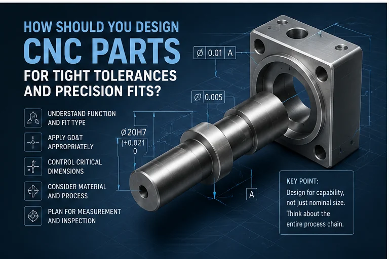
Tight tolerances and precision fits are essential when CNC parts must locate, guide, rotate, seal, press together, slide, align optical elements, position sensors, or maintain repeatable assembly. However, a tighter dimension is not automatically a better dimension. Every reduced tolerance increases machining, inspection, process-control, and scrap risk, and it may still fail if the datum structure, surface finish, temperature, material condition, coating thickness, or assembly force is not defined correctly.
Precision design begins with function. Engineers should identify which features control alignment, motion, sealing, preload, concentricity, or interchangeability, and then assign tolerances only where those functions require them. The complete tolerance stack, manufacturing sequence, heat treatment, surface treatment, inspection method, and assembly condition must be considered together.
A shaft that is within diameter tolerance can still bind if it is out of round. A bore can pass a plug gauge but fail if it is misaligned with the datum. A press fit can loosen after anodizing, heat cycling, or material creep. A bearing seat can be dimensionally correct but fail because the surface roughness, chamfer, or shoulder geometry is wrong. Precision fits therefore depend on geometry and surface condition, not size alone.
RapidMFGPro evaluates tight-tolerance CNC projects from a supplier-matching perspective. The review considers material, geometry, datum structure, tolerance stack, fit class, machining process, heat treatment, finishing, inspection method, production quantity, documentation, and assembly requirement before identifying suppliers with suitable milling, turning, grinding, honing, EDM, metrology, and quality-control capabilities.
This guide explains how to design CNC parts for tight tolerances and precision fits without adding unnecessary cost or creating requirements that are difficult to manufacture and inspect consistently.
Start with the Functional Requirement
Tight tolerances should be assigned only after the designer understands what the part must do in the final assembly.
Alignment Function
Alignment features control the relative position of components such as bearings, sensors, lenses, guides, rails, and mating housings.
Position, concentricity, profile, perpendicularity, and datum relationships may matter more than the nominal size.
Motion Function
Sliding, rotating, and reciprocating parts need controlled clearance, roundness, straightness, surface finish, lubrication, and temperature allowance.
Diameter tolerance alone does not define smooth motion.
Sealing Function
Sealing parts need flatness, groove geometry, surface finish, compression, and positional control.
A very tight linear tolerance cannot compensate for waviness or damaged sealing surfaces.
Interchangeability Function
Production parts must assemble without selective matching when interchangeability is required.
Tolerance limits should reflect process capability and the expected distribution of mating parts.
| Function | Critical Design Control | Common Failure |
|---|---|---|
| Bearing alignment | Coaxiality, position, shoulder squareness | Noise, wear, or bearing preload |
| Sliding guide | Clearance, straightness, roughness | Binding or excessive play |
| O-ring seal | Groove size, surface finish, concentricity | Leakage or seal damage |
| Optical alignment | Datum position, tilt, runout | Image or beam misalignment |
| Press-fit insert | Interference, roundness, wall support | Loose fit or cracking |
| Assembly interchangeability | Tolerance stack and process capability | Selective assembly or rework |
What Is a Tight Tolerance?
A tight tolerance is a dimensional or geometric requirement that is narrow relative to the part size, material behavior, process capability, or normal manufacturing variation.
Relative Definition
A ±0.02 mm tolerance may be routine on a short ground shaft but difficult on a large thin aluminum plate.
Tightness must be evaluated in context.
Process-Dependent Definition
Turning, milling, grinding, honing, lapping, EDM, and reaming have different natural capability ranges.
A tolerance that is easy with grinding may be expensive with milling.
Feature-Dependent Definition
A short accessible bore is easier to control than a deep blind bore of the same diameter.
Feature depth, aspect ratio, wall thickness, and access affect practical capability.
What Is a Precision Fit?
A precision fit is the controlled relationship between two mating features, usually a shaft and bore, where clearance or interference determines assembly and function.
Clearance Fit
A clearance fit guarantees space between mating parts.
It is used for sliding, rotation, assembly access, and thermal expansion.
Transition Fit
A transition fit may produce small clearance or small interference depending on actual part sizes.
It is used for accurate location where light assembly force is acceptable.
Interference Fit
An interference fit requires pressing, shrinking, or heating one component for assembly.
It is used for torque transfer, permanent retention, and bearing or bushing installation.
Why Size Tolerance Alone Is Not Enough
Precision fits fail when geometric error, surface finish, or datum misalignment consumes the intended clearance.
Roundness
A bore may be within the upper and lower diameter limits but have lobes that interfere with the shaft.
Roundness should be controlled when smooth rotation or sealing depends on the shape.
Straightness
A long shaft or bore can bend while every local diameter measurement remains acceptable.
Straightness becomes important for long engagement lengths.
Cylindricity
Cylindricity controls the complete three-dimensional shape of a cylindrical feature.
It can be more meaningful than separate size, roundness, and straightness limits.
Surface Roughness
Surface peaks occupy part of the nominal clearance and can be crushed during assembly.
Roughness should match the fit and motion requirement.
How Should Tolerances Be Allocated?
Tolerance allocation divides the allowable functional variation across the contributing dimensions and geometries.
Identify the Functional Stack
Trace the dimensions from one functional interface to the other.
Include component dimensions, geometric errors, assembly gaps, coatings, and thermal changes.
Assign More Tolerance to Stable Features
Features produced in one setup on rigid geometry can often hold tighter limits than flexible or post-treated features.
The stack should reflect manufacturing reality.
Avoid Equal Allocation by Default
Dividing total tolerance equally among all dimensions is simple but not always economical.
Critical and difficult features should be allocated based on process capability and functional sensitivity.
Reserve Assembly Margin
The entire allowable variation should not be consumed by nominal part dimensions.
Reserve margin for surface finish, temperature, contamination, and long-term wear.
How Does Worst-Case Stack-Up Work?
Worst-case analysis assumes every contributing dimension reaches the limit that produces the most unfavorable assembly condition.
Maximum Material Condition
Maximum material condition represents the condition containing the greatest amount of material.
For an external shaft, it is the largest permitted size. For an internal bore, it is the smallest permitted size.
Guaranteed Assembly
Worst-case allocation is appropriate when every part must assemble without selection.
It is conservative and can create unnecessarily expensive component tolerances.
Safety-Critical Interfaces
Press fits, sealing, collision clearance, and safety-related assemblies often justify worst-case analysis.
The cost should be accepted because failure risk is high.
When Is Statistical Tolerancing Useful?
Statistical tolerancing considers the expected distribution of process variation rather than assuming every dimension reaches its worst limit simultaneously.
Stable Production Processes
Statistical methods require measured process capability and controlled production.
They should not be used only to justify a difficult design.
High-Volume Assemblies
Large production data sets allow meaningful estimation of stack behavior.
Pilot runs and capability studies are important.
Risk Controls
Statistical tolerancing may permit a small probability of assembly failure.
Screening, adjustment, or process monitoring should manage that risk.
How Should Datum Features Be Selected?
Datums create the coordinate system used to manufacture, inspect, and assemble the part.
Match the Assembly Interface
Primary datums should represent the surfaces that locate the part in the final product.
Inspection then measures the features in the same relationship that matters in use.
Use Stable Surfaces
Large flat bases, bearing seats, precision bores, and reinforced faces make repeatable datums.
Flexible walls and rough cast surfaces are poor choices.
Avoid Conflicting Datum Schemes
Multiple drawings or process notes should not define different primary references for the same critical features.
Manufacturing and inspection must use a consistent datum structure.
Consider Fixture Access
Datum features must remain accessible to machine fixtures and inspection equipment.
Hidden datums create expensive custom tooling.
How Should a Datum Reference Frame Be Built?
A datum reference frame commonly uses primary, secondary, and tertiary datums to constrain movement in a controlled sequence.
Primary Datum
The primary datum establishes the main orientation and removes three degrees of freedom.
It is usually the largest stable mounting face or axis.
Secondary Datum
The secondary datum establishes a second orientation and removes two additional degrees of freedom.
It may be a side face, bore, or second axis.
Tertiary Datum
The tertiary datum completes location by removing the final degree of freedom.
It should not over-constrain the part unnecessarily.
When Should Position Tolerance Be Used?
Position tolerance controls the location of holes, pins, slots, and other features relative to datums.
Bolt-Hole Patterns
Position tolerance controls the complete hole pattern more effectively than separate coordinate tolerances.
It supports functional-gauge inspection.
Dowel Holes
Dowel holes require tighter positional control than ordinary clearance holes.
Size, position, perpendicularity, and fit should be coordinated.
Bonus Tolerance
Maximum material condition can provide additional positional tolerance as the actual feature departs from MMC.
This can reduce cost while preserving assembly.
Composite Position
Composite position can separately control pattern location and feature-to-feature relationship.
It is useful for precise connector, manifold, and fastener patterns.
When Should Profile Tolerance Be Used?
Profile tolerance controls complex surfaces, contours, and feature relationships using one clear requirement.
Complex Milled Surfaces
Contoured housings, turbine-like surfaces, optical mounts, and ergonomic shapes can be controlled with profile.
This avoids many separate coordinate dimensions.
Thin or Flexible Parts
Profile can control the overall shape of a thin wall or sheet-like machined structure.
The drawing should define free-state or restrained-state inspection.
Assembly Interfaces
Profile relative to functional datums ensures that the complete mating surface is correctly located.
It is useful for gaskets, covers, and complex seals.
How Should Flatness Be Specified?
Flatness controls one surface independently of datums. It should be applied only where flatness directly affects function.
Sealing Faces
Gasket and O-ring interfaces may require flatness to maintain uniform compression.
Surface finish and local waviness should also be controlled.
Mounting Bases
A flat base reduces rocking and alignment error.
Bolting can distort a thin base even when free-state flatness is acceptable.
Large Surfaces
Tight flatness across a large area can require stress-relieved material, grinding, lapping, and controlled inspection.
Local flatness zones may be more economical.
How Should Perpendicularity Be Specified?
Perpendicularity controls orientation between a feature and a datum.
Shoulder Faces
Bearing shoulders should be square to the shaft axis.
Angular error can create uneven preload and shortened bearing life.
Bores to Mounting Faces
A bore can have correct diameter but still tilt relative to the mounting surface.
Perpendicularity controls this relationship.
Threaded Holes
A threaded hole that is tilted can pull the assembly out of alignment.
Position and orientation should be considered together.
How Should Runout Be Used?
Runout controls variation of rotating surfaces relative to a datum axis.
Circular Runout
Circular runout controls each circular cross-section during rotation.
It is used for bearing seats, seal diameters, and rotating faces.
Total Runout
Total runout controls the complete surface along its length.
It limits combined roundness, straightness, coaxiality, and taper effects.
Datum-Axis Quality
Runout is meaningful only when the datum axis is stable and functional.
A poor datum bore can create misleading results.
How Should Hole Tolerances Be Designed?
Hole tolerance depends on whether the hole provides clearance, location, bearing support, sealing, flow, or threading.
Clearance Holes
Clearance holes should allow assembly under the worst positional and size conditions.
They usually do not need reamed tolerances.
Reamed Holes
Reaming improves size and finish on precision dowel, bushing, and shaft holes.
Reamer runout, stock allowance, and tool wear should be controlled.
Bored Holes
CNC boring supports precise diameter, position, and alignment in larger holes.
Long bores may still need honing or grinding.
Honed Holes
Honing improves size, roundness, straightness, and surface texture.
It is common for hydraulic, pneumatic, and bearing applications.
How Should Shaft Tolerances Be Designed?
Shaft design should account for diameter, roundness, straightness, runout, surface finish, shoulder geometry, and coating.
Turned Shafts
Precision turning can produce good diameter and concentricity in one setup.
Tool wear and thermal growth must be monitored.
Ground Shafts
Cylindrical grinding provides tighter size, roundness, and finish.
Heat treatment should normally occur before final grinding.
Long Slender Shafts
Long shafts bend under cutting and inspection force.
Steady rests, centers, multiple operations, and straightness control may be required.
Coated Shafts
Plating, anodizing, thermal spray, and hard coating add thickness and may require final grinding.
The drawing should define final diameter after coating.
How Should Dowel Fits Be Designed?
Dowel pins provide repeatable location and should not be used to compensate for an unclear datum strategy.
One Round and One Diamond Pin
A round pin locates in two directions while a diamond pin relieves over-constraint in one direction.
This arrangement accommodates hole-spacing variation.
Press-Fit Side
One component commonly retains the dowel with an interference fit.
Wall thickness and insertion force should support the fit.
Slip-Fit Side
The mating component uses a controlled clearance fit for assembly and disassembly.
Burrs, coating, and contamination must not consume the clearance.
Lead-In Chamfer
Chamfers guide the dowel and prevent shaving material.
The chamfer should not reduce the functional locating length excessively.
How Should Bearing Fits Be Designed?
Bearing fits depend on load direction, ring rotation, temperature, housing material, wall thickness, assembly method, and service life.
Rotating Load
A bearing ring exposed to a rotating load usually needs sufficient interference to prevent creep.
The required fit depends on bearing size and load.
Stationary Load
A ring exposed to a stationary load may use a lighter fit or clearance.
Assembly and thermal growth should be considered.
Housing Stiffness
Thin aluminum or plastic housings expand more under press fit than steel housings.
Excess interference can distort the bearing race.
Shoulder and Fillet Geometry
Bearing shoulders need correct squareness and relief.
A large shaft fillet can interfere with the bearing chamfer.
How Should Bushing Fits Be Designed?
Bushing performance depends on interference, wall thickness, lubrication, final bore size, and housing stiffness.
Press-Fit Distortion
Pressing a thin bushing into a housing reduces the internal diameter.
Final bore size may need to be measured or machined after installation.
Split Bushings
Split bushings change shape during installation.
Housing bore size and roundness are especially important.
Flanged Bushings
The flange controls axial location and carries thrust.
Shoulder flatness and perpendicularity should be controlled.
How Should Sliding Fits Be Designed?
Sliding fits require enough clearance for motion while limiting play, vibration, and misalignment.
Running Clearance
Clearance should include manufacturing variation, thermal expansion, lubrication film, particles, and wear.
Zero-clearance design usually causes binding.
Surface Finish
Rough surfaces increase friction and wear.
Extremely smooth surfaces may retain less lubricant in some applications.
Material Pairing
Similar metals can gall under sliding contact.
Dissimilar materials, coatings, or bearing plastics may improve performance.
Contamination Allowance
Dust, chips, and process debris can consume small clearances.
Seals, wipers, and cleaning access should be included.
How Should Press Fits Be Designed?
Press fits transfer load through elastic and plastic contact pressure. They should be designed from material properties and geometry rather than one generic interference value.
Interference Amount
More interference increases retention but also assembly force and stress.
Excess interference can crack the housing or permanently deform the inserted part.
Wall Thickness
Thin bosses expand more than thick housings.
Local reinforcement may be required around the fit.
Surface Roughness
Roughness peaks flatten during pressing and reduce effective interference.
Surface texture should be included in fit validation.
Assembly Temperature
Heating the housing or cooling the insert reduces assembly force.
The final room-temperature interference remains unchanged.
How Should Threaded Fits Be Designed?
Threaded interfaces require control of size, pitch diameter, position, perpendicularity, surface finish, coating, lubrication, and torque.
Thread Class
Thread class should reflect required fit and manufacturing capability.
Excessively tight classes increase tapping and gauging cost.
Coating Allowance
Zinc plating, electroless nickel, anodizing, and paint change thread fit.
Masking or pre-finish compensation may be required.
Thread Position
A correct thread size does not guarantee correct hole location.
Position relative to functional datums should be controlled.
Assembly Torque
Coating and lubrication change thread friction.
Torque should be validated in the finished condition.
How Should Sealing Fits Be Designed?
Precision sealing depends on geometry, surface texture, material compression, pressure, temperature, and assembly preload.
O-Ring Glands
Groove width, depth, corner radius, squeeze, stretch, and surface finish must work together.
Tolerance stack should include both groove and mating diameter.
Face Seals
Flatness and parallelism determine uniform gasket compression.
Bolt pattern and flange stiffness affect the final seal.
Metal-to-Metal Seals
Metal seals need tightly controlled geometry, hardness, surface finish, and contact load.
Lapping and leak testing may be required.
How Does Surface Finish Affect Precision Fits?
Surface finish affects friction, wear, sealing, contact pressure, lubrication, and measured size.
Ra Is Not the Complete Surface
Two surfaces with the same Ra can have different peak shape, direction, waviness, and bearing area.
The functional process should guide the finish requirement.
Lay Direction
Grinding and turning create directional texture.
Lay direction can influence sealing and sliding.
Waviness
Waviness is a larger-scale deviation than roughness.
It can cause leakage or uneven bearing contact even when Ra is acceptable.
Plateau Finishes
Honing can create a plateau surface with load-bearing areas and lubricant-retaining valleys.
This is useful for cylinders and sliding seals.
How Does Material Choice Affect Tolerance?
Material stiffness, thermal expansion, residual stress, hardness, moisture absorption, and machinability determine how well dimensions remain stable.
Aluminum
Aluminum machines easily but expands significantly with temperature and can release residual stress.
Stress-relieved stock and controlled inspection temperature improve stability.
Steel
Steel provides higher stiffness and stable bearing surfaces.
Heat treatment and grinding sequence affect final accuracy.
Titanium
Titanium has lower modulus than steel and retains cutting heat.
Thin or flexible features may spring during machining.
Engineering Plastics
Plastics expand more with temperature and may absorb moisture or creep.
Metal-level tolerance expectations should not be transferred automatically.
| Material Family | Main Advantage | Main Tolerance Risk | Typical Control |
|---|---|---|---|
| Aluminum | Good machinability | Thermal expansion and residual stress | Temperature control and stress-relieved stock |
| Carbon or alloy steel | High stiffness | Heat-treatment distortion | Finish machining after heat treatment |
| Stainless steel | Corrosion resistance | Work hardening and heat | Stable tooling and controlled cutting |
| Titanium | High specific strength | Springback and low thermal conductivity | Rigid support and light finishing cuts |
| Copper | Electrical and thermal conductivity | Softness, burrs, and clamping marks | Sharp tools and broad support |
| Engineering plastic | Low weight and insulation | Moisture, creep, and thermal change | Conditioning and realistic tolerances |
How Does Heat Treatment Affect Precision?
Heat treatment changes hardness, residual stress, dimensions, straightness, and surface condition.
Quenching Distortion
Uneven heating and cooling cause bow, twist, taper, and ovality.
Final grinding or honing may be required.
Stress Relief
Stress relief before final machining reduces later movement.
The cycle must remain compatible with required mechanical properties.
Aging
Aluminum and precipitation-hardening alloys may move during artificial or natural aging.
Final tolerance should be cut after the critical thermal cycle.
Case Hardening
Carburizing and nitriding change surface hardness and can distort thin or asymmetric parts.
Grind allowance should be included before treatment.
How Do Surface Treatments Affect Fits?
Surface treatments change dimensions, friction, hardness, conductivity, roughness, and corrosion behavior.
Anodizing
Anodizing makes external features larger and internal features smaller.
Bearing seats, threads, and dowel holes may require masking or allowance.
Electroless Nickel
Electroless nickel adds relatively uniform thickness and can be ground or lapped after plating.
Final coating thickness should remain after finishing.
Zinc Plating
Zinc changes thread fit and press-fit dimensions.
Passivation and sealer also change friction.
Powder Coating and Paint
Organic coatings add substantial thickness and should normally be masked from precision fits.
Raised mask edges can also interfere with assembly.
How Does Temperature Affect Precision Fits?
Temperature changes both part dimensions and the clearance or interference between dissimilar materials.
Inspection Temperature
Precision dimensions should be measured after the part stabilizes at a controlled temperature.
Warm parts can appear outside or inside tolerance incorrectly.
Operating Temperature
A fit designed at room temperature may tighten or loosen in service.
Differential expansion between aluminum, steel, plastic, and copper should be calculated.
Assembly Temperature
Shrink fitting uses controlled heating or cooling to create temporary assembly clearance.
Final interference develops when temperatures equalize.
Thermal Cycling
Repeated temperature change can loosen inserts, alter preload, and move precision components.
Environmental testing may be required.
How Does Clamping Affect Tight Tolerances?
Clamping can distort the part during machining and inspection, creating dimensions that change after release.
Point Loading
Small hard contact areas create local dents and bending.
Broad soft jaws and support nests distribute force.
Over-Constraint
Too many fixture contacts can force a warped part into an artificial shape.
The part springs back after unclamping.
Datum Repeatability
Fixture contacts should locate the same datum structure used on the drawing.
Re-clamping error otherwise becomes part of the tolerance stack.
Inspection Fixturing
Inspection clamps can hide actual free-state deformation.
The drawing should define allowed restraint.
How Does Machine Setup Affect Accuracy?
Setup count, machine condition, tool length, probing, fixture design, and thermal stability determine practical accuracy.
Single-Setup Machining
Machining related features in one setup reduces datum-transfer error.
Multi-axis machining can improve positional relationships.
Multiple Setups
Some parts require several orientations.
Precision locating features and in-process probing reduce re-clamping error.
Machine Thermal Stability
Spindle, ball screw, coolant, and shop temperature change during production.
Warm-up cycles and compensation support repeatability.
Tool Wear
Diameter and surface finish drift as tools wear.
Tool-life limits and offset correction should be planned.
When Is Precision Turning Suitable?
Precision turning is suitable for shafts, pins, sleeves, bushings, threads, sealing diameters, and concentric features.
Concentric Features
Multiple diameters and faces machined in one chucking can maintain strong concentricity.
Re-chucking introduces runout.
Fine Boring
Boring bars can control internal diameter and alignment.
Long small bores may require honing.
Soft and Hard Turning
Soft turning occurs before heat treatment, while hard turning can finish hardened steel.
Grinding may still be required for the tightest roundness and finish.
When Is Precision Milling Suitable?
Precision milling is suitable for datums, pockets, hole patterns, profiles, slots, and multi-face relationships.
Rigid Prismatic Parts
Thick, well-supported parts hold milling tolerances more consistently than thin or flexible geometry.
Stable fixture design is essential.
Multi-Axis Relationships
4-axis and 5-axis machining can produce related features with fewer setups.
Machine calibration and probing affect final accuracy.
Finish Pass Strategy
Uniform stock, sharp tools, and stable engagement improve accuracy and surface finish.
Heavy roughing should not be combined with the final precision cut.
When Is Grinding Required?
Grinding is used when turning or milling cannot consistently achieve the required size, roundness, flatness, hardness, or surface finish.
Cylindrical Grinding
Cylindrical grinding controls shafts, bearing seats, seal diameters, and roundness.
Centers and datum surfaces must be prepared correctly.
Surface Grinding
Surface grinding controls flatness, parallelism, thickness, and surface texture.
Magnetic chuck force can distort thin steel parts.
Internal Grinding
Internal grinding controls hardened bores and bearing seats.
Wheel access and bore length affect capability.
When Are Honing and Lapping Required?
Honing and lapping are used when the fit depends on very low roughness, precise geometry, or sealing contact.
Honing
Honing improves bore roundness, straightness, size, and lubricant-retaining texture.
It is common for hydraulic cylinders and valve bores.
Lapping
Lapping produces very flat and smooth mating surfaces.
It is used for mechanical seals, valves, optical mounts, and gauges.
Matching and Interchangeability
Some lapped assemblies are selectively matched.
If full interchangeability is required, the drawing and process plan must state it.
When Is EDM Useful?
Electrical discharge machining is useful for hard materials, sharp internal features, narrow slots, and geometry that cannot be reached with rotating cutters.
Wire EDM
Wire EDM controls profiles, slots, punches, dies, and hardened precision components.
Start holes, wire access, recast layer, and surface finish should be considered.
Sinker EDM
Sinker EDM creates cavities, ribs, and sharp internal features.
Electrode wear affects final accuracy.
Post-EDM Finishing
Recast layers and microcracks may require polishing or removal in fatigue-critical parts.
Final surface requirements should be specified.
How Should Process Capability Be Considered?
A tolerance is sustainable only when the supplier’s process is capable and stable over the required production quantity.
Short-Term Capability
A supplier may produce a few good samples through adjustment and sorting.
This does not prove stable production capability.
Long-Term Capability
Long-term capability includes tool wear, machine drift, operators, material lots, temperature, and maintenance.
Production tolerances should reflect this variation.
Capability Indices
Cp, Cpk, Pp, and Ppk may be used to evaluate process spread and centering.
The required index should be agreed with the customer.
Measurement-System Capability
Capability data is unreliable when the gauge contributes too much variation.
Gauge repeatability and reproducibility should be checked.
How Should Inspection Be Planned?
Inspection method, datum simulation, measurement force, temperature, and sampling should be defined before production.
In-Process Inspection
Probes, bore gauges, micrometers, air gauges, and tool setters can detect drift before parts are completed.
In-process checks reduce scrap.
Final Inspection
Final inspection should occur after all heat treatment, coating, cleaning, and stabilization.
Pre-finish results do not prove final fit.
Sampling Plan
Prototype, first-article, and production sampling requirements should be separated.
Critical fits may require 100 percent gauging.
Functional Inspection
Assembly, leakage, rotation, insertion force, torque, and runout tests may provide more useful evidence than dimensions alone.
The functional fixture should represent real assembly.
Which Measuring Tools Are Common?
The tool should match the feature, tolerance, access, surface, and measurement uncertainty.
Micrometers
Micrometers measure external thickness and diameter with controlled contact.
Operator force and part temperature affect results.
Bore Gauges
Dial and digital bore gauges compare internal diameter and reveal taper or ovality.
Calibration and alignment are essential.
Air Gauges
Air gauging provides fast noncontact or low-contact bore measurement for high-volume precision production.
Clean dry air and master standards are required.
Coordinate Measuring Machines
CMMs measure position, profile, orientation, and complex geometry.
Probe qualification and datum setup affect accuracy.
Optical Systems
Vision and scanning systems measure small, flexible, or delicate features without strong contact.
Reflectivity and edge interpretation require control.
How Should Measurement Uncertainty Be Managed?
The measurement system must be accurate enough to distinguish acceptable and unacceptable parts reliably.
Gauge Resolution
A gauge with coarse resolution cannot support a narrow tolerance.
Resolution is only one part of uncertainty.
Calibration
Instruments and masters should be calibrated at defined intervals.
Traceability should match customer requirements.
Operator Variation
Contact force, alignment, datum cleaning, and reading technique create variation.
Work instructions and training improve consistency.
Environmental Variation
Temperature, humidity, vibration, and cleanliness affect precision measurement.
A controlled inspection area may be required.
How Should First-Article Inspection Be Used?
First-article inspection verifies that the manufacturing process can produce the complete drawing before full production.
Full Dimensional Review
The first article should include all drawing dimensions and geometric requirements when requested.
Ballooned drawings improve traceability.
Material and Process Verification
Material certificates, heat treatment, surface finish, coating, and special-process records should be included.
Dimensional conformity alone is not enough.
Assembly Validation
Mating parts should be assembled and tested before production release.
This reveals stack-up and finish issues.
How Should Prototype and Production Tolerances Differ?
Prototype parts may use machining strategies that are not economical or stable for production.
Prototype Adjustment
Individual parts can be measured and corrected manually.
This can hide a process that is not naturally capable.
Pilot Production
A pilot run reveals tool wear, material variation, fixture repeatability, and inspection time.
Capability data should be collected.
Production Release
Production tolerances should be supported by repeatable tooling, offsets, gauges, and control plans.
Selective fitting should be stated if it remains part of the process.
How Can Tight-Tolerance Cost Be Reduced?
Cost is reduced by assigning tight tolerances selectively, aligning them with natural process capability, and simplifying inspection.
Use Functional Tolerances Only
Tighten only the features that control fit, alignment, seal, or motion.
Relax hidden and nonfunctional dimensions.
Use Common Tool Sizes
Standard reamers, drills, bearings, dowels, bushings, and gauges reduce tooling cost.
Custom sizes increase lead time and inspection complexity.
Machine Related Features Together
One-setup machining improves feature relationships and reduces datum-transfer error.
Part orientation should support this strategy.
Use Geometric Tolerancing Efficiently
Position, profile, and MMC can preserve function while providing more manufacturing freedom.
Overly restrictive coordinate tolerances often increase cost.
What Common Design Mistakes Increase Cost?
Many precision-part costs come from requirements that are redundant, contradictory, or unrelated to function.
Tight General Tolerance Blocks
Applying one tight default tolerance to every dimension creates unnecessary inspection and scrap risk.
General tolerances should remain practical.
Duplicate Controls
Size, position, profile, concentricity, and runout may overlap if applied without a clear strategy.
Redundant controls create interpretation problems.
Unmeasurable Requirements
Hidden surfaces, inaccessible datums, and extremely small zones may be impossible to inspect directly.
Measurement planning should occur during design.
Ignoring Surface Treatment
A tolerance applied before coating may be impossible after coating.
Final-condition requirements should be clear.
What Should Be Shown on the Drawing?
A precision-part drawing should define functional datums, fit requirements, geometric controls, final finish, inspection condition, and acceptance criteria.
Fit Designation
State shaft and hole limits, ISO fit, ANSI fit, or explicit minimum and maximum clearance or interference.
Avoid relying on general terms such as tight fit.
Datum Structure
Define primary, secondary, and tertiary datums that match assembly.
Critical features should reference the same functional frame.
Geometric Controls
Use position, profile, runout, perpendicularity, flatness, roundness, or cylindricity as required.
Avoid redundant controls.
Surface Finish
State roughness and lay where friction, sealing, or wear depends on it.
Ra alone may not define the complete surface.
Final Condition
State whether dimensions apply after heat treatment, plating, anodizing, painting, grinding, or assembly.
Inspection temperature and restraint may also need definition.
What Should Be Included in the RFQ?
A complete RFQ allows suppliers to evaluate process capability, tooling, inspection, and production risk accurately.
3D Model and Controlled Drawing
Provide both the model and drawing with revision control.
The drawing defines acceptance.
Material and Condition
State grade, temper, hardness, stock form, heat treatment, and certification.
Material condition affects dimensional stability.
Fit Function
Describe sliding, bearing, sealing, press-fit, optical, or alignment requirements.
This helps the supplier interpret the tolerance correctly.
Quantity
State prototype quantity, first order, and annual demand.
Quantity affects fixture, gauge, and process-control investment.
Inspection Requirement
State first-article, CMM report, capability study, gauge R&R, 100 percent inspection, or sampling requirements.
Required documentation should be included before quotation.
How Does RapidMFGPro Evaluate Precision Projects?
RapidMFGPro evaluates precision CNC projects by connecting the function, datum structure, fit, process capability, finishing, inspection, and supplier resources required for the actual part.
Function Review
The review begins with alignment, motion, sealing, preload, interchangeability, and service environment.
This identifies which tolerances are truly critical.
Tolerance Review
Size, geometry, stack-up, coating allowance, thermal change, and inspection condition are reviewed together.
Redundant or conflicting requirements are identified before production.
Process Review
Milling, turning, reaming, boring, grinding, honing, lapping, EDM, heat treatment, and coating are compared.
The process route is matched to the tolerance and quantity.
Supplier Matching
Suppliers are compared according to precision-machining experience, machine capability, thermal control, grinding, honing, metrology, in-process probing, gauge control, and production capacity.
A supplier suitable for ±0.10 mm brackets may not be suitable for bearing bores, optical mounts, or matched valve parts.
Quality Review
The quality review confirms material traceability, final dimensions, GD&T, surface finish, coating, first-article inspection, functional fit, and packaging.
The inspection plan should be agreed before production.
How Should Supplier Capability Be Evaluated?
Precision capability depends on machines, fixtures, tools, thermal control, measurement systems, operators, process discipline, and quality records.
Similar-Part Experience
The supplier should show experience with similar material, feature size, tolerance, and geometry.
General CNC capability is not enough.
Machine and Process Capability
Spindle condition, axis accuracy, probing, grinding, honing, and environmental control should match the requirement.
Capability studies may be requested.
Fixture Capability
The supplier should control datum repeatability and avoid part distortion.
Dedicated fixtures may be justified for production.
Metrology Capability
CMMs, air gauges, bore gauges, roundness testers, profilometers, optical systems, and masters may be required.
Measurement uncertainty should be appropriate for the tolerance.
Documentation Capability
First-article reports, capability data, control plans, gauge records, certificates, and traceability may be required.
Documentation scope should be agreed in the RFQ.
How Should the Final Design Decision Be Made?
The final design should provide enough tolerance for stable manufacturing while protecting the actual assembly function.
Confirm the Fit Requirement
Define minimum and maximum clearance or interference in the final operating condition.
Include coating, temperature, and wear.
Confirm the Datum Strategy
Use assembly-representative datums that can be machined and inspected reliably.
Related features should share a consistent datum frame.
Confirm the Process Route
Match the tolerance to turning, milling, reaming, grinding, honing, lapping, or EDM.
Do not force a standard process to achieve an unnatural tolerance.
Confirm Inspection Feasibility
Ensure the feature can be measured with acceptable uncertainty and without distortion.
Functional gauges may simplify production control.
Confirm Production Capability
Pilot data should demonstrate that the process remains centered and stable over time.
The tolerance should not depend on manual correction of every part.
| Design Action | Main Benefit | Potential Tradeoff |
|---|---|---|
| Use functional datums | Improves assembly alignment | May require fixture redesign |
| Apply tight tolerances selectively | Reduces cost and scrap | Requires functional analysis |
| Use standard fit classes | Simplifies tooling and gauging | May limit custom behavior |
| Finish machine after heat treatment | Improves final stability | Adds operations |
| Mask precision fits before coating | Prevents buildup interference | Creates bare-metal areas |
| Use functional gauges | Speeds production inspection | Requires gauge investment |
Frequently Asked Questions
These questions address common decisions when designing CNC parts for tight tolerances and precision fits.
How Tight Can CNC Machining Hold?
Capability depends on material, geometry, feature size, machine, setup, temperature, process, and inspection. No single value applies to every CNC part.
Is a Tighter Tolerance Always Better?
No. Tighter tolerances increase cost and can reduce yield without improving function.
What Is the Difference between Clearance and Interference Fit?
A clearance fit always leaves space between parts. An interference fit requires force or thermal assembly because the shaft is larger than the bore.
Should Bearing Bores Be Reamed or Ground?
Reaming is suitable for many precision bores. Grinding or honing is preferred when tighter size, roundness, straightness, or finish is required.
Should Dimensions Apply before or after Coating?
Functional fit dimensions should normally apply after the final coating unless masking or post-machining is specified.
Can CMM Inspection Replace Functional Gauging?
CMM data is useful for geometry, but functional gauges can verify assembly more quickly. Many projects benefit from both.
How Does Temperature Affect a Precision Fit?
Temperature changes both part sizes and the clearance between dissimilar materials. Operating temperature should be included in fit design.
When Is 100 Percent Inspection Needed?
It may be required for safety-critical fits, low-capability processes, high-value assemblies, or features that cannot be protected through sampling alone.
Conclusion
Tight tolerances and precision fits should be designed from function, datum structure, tolerance stack, geometric form, surface finish, material stability, temperature, heat treatment, coating, and inspection. Size tolerance alone cannot guarantee alignment, motion, sealing, or retention. The most reliable designs use functional datums, standard fit systems, selective tight tolerances, suitable finishing processes, and measurement methods with adequate uncertainty. RapidMFGPro supports precision projects by reviewing the design and matching it with suppliers whose machining, grinding, honing, metrology, process-control, and quality capabilities fit the actual tolerance and production requirement.
Need Help Reviewing a Custom Part?
Share your CAD file and requirements to request supplier matching. Supplier capability and commercial terms must be verified before order placement.
Request Supplier Match