Time to read: 6 min
Large Part Injection Molding: Engineering Design and Sourcing Guide
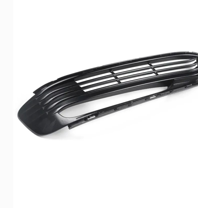
Large part injection molding is used for housings, equipment panels, automotive components, appliance parts, storage systems, medical equipment covers, and industrial structures that are too large for standard molds and presses. Scaling up a molded part changes more than machine size. It increases sensitivity to flow length, cooling time, warpage, clamping force, mold handling, and logistics.
This guide explains how to design and source large molded parts, when injection molding is appropriate, and what information a manufacturer needs to evaluate tooling and production risk.
What Makes a Molded Part “Large”?
A part may be considered large because of its overall dimensions, projected area, shot weight, flow length, or mold size. A wide thin panel can require a very large press even when it contains little material because the projected area creates high separating force on the mold. A thick compact component may require more shot capacity and longer cooling.
Large molds also need suitable cranes, storage, maintenance equipment, and transport. Supplier selection must consider the complete production system, not only the nominal tonnage of the injection molding machine.
Material Selection
Common materials include polypropylene, ABS, polycarbonate blends, nylon, polyethylene, and glass-filled engineering plastics. Material choice depends on stiffness, impact resistance, heat, chemicals, UV exposure, appearance, flame performance, and cost.
Large parts often need greater stiffness than small parts. Increasing wall thickness is one option, but it adds weight, cooling time, and sink risk. Ribs, curves, boxed sections, and glass-filled materials can improve stiffness more efficiently. Filled materials may increase tool wear and create directional shrinkage, so fiber orientation should be considered.
Use Consistent Wall Thickness
Uniform walls help the melt flow and cool consistently. Thick sections cool slowly and can create sink marks, voids, and differential shrinkage. Thin sections may freeze before the cavity fills. Gradual transitions are preferable to abrupt changes.
Large flat surfaces are especially prone to warpage. Gentle curvature, ribs, and perimeter flanges can improve stability. Designers should avoid making every rib too thick; a rib base is often designed as a fraction of the adjacent wall to reduce sink on the opposite surface.
Plan Flow Length and Gate Location
Molten plastic must travel from the gate through the entire cavity before freezing. Large parts may need multiple gates, hot runners, sequential valve gates, or specialized flow leaders. Gate location affects weld lines, fiber orientation, pressure, and cosmetic appearance.
Weld lines should be kept away from highly loaded or visible areas when possible. Air traps need vents. The supplier may use mold-flow simulation to evaluate pressure, temperature, fill balance, clamp force, and cooling. Simulation does not eliminate testing, but it can identify major risks before steel is cut.
Draft, Radii, and Part Release
Large surfaces create significant friction during ejection. Adequate draft reduces scuffing and ejection force. Textured surfaces require more draft than polished surfaces. Deep ribs and bosses may also need greater draft.
Internal corners should have radii to improve flow and reduce stress. Sharp corners are difficult to machine in the mold and can crack under load. The parting line and ejection system should be reviewed early because ejector marks and flash may be visible on large panels.
Control Warpage with Geometry and Cooling
Warpage is one of the main challenges in large part injection molding. It results from uneven shrinkage, fiber orientation, temperature gradients, and residual stress. Balanced wall thickness, symmetric ribs, suitable gate locations, and uniform cooling help reduce it.
Critical flatness requirements should be realistic. A large cover may function correctly with controlled mounting points even if the free-state panel is not perfectly flat. Fixture-based inspection or assembly testing may be more meaningful than measuring every surface against a nominal plane.
Bosses, Inserts, and Fastening
Large parts often include screw bosses, metal inserts, clips, hinges, and attachment points. Bosses should be supported by ribs rather than connected to a thick solid base. Heat-set or molded-in inserts can provide durable threads, but the process sequence and pull-out load must be defined.
Snap fits can reduce hardware, but long snap features may be sensitive to material variation and assembly force. Service requirements should be considered. A permanent snap is different from a feature that must be opened repeatedly.
Tooling Strategy
A large production mold can be a major investment. Tool steel, cavity count, hot-runner system, slides, lifters, cooling channels, and expected life all affect cost. For lower volumes, aluminum tooling or simplified molds may be considered, but cycle time and life must match the business case.
Tool ownership, maintenance, storage, spare components, and change procedures should be defined in the sourcing agreement. If the design is likely to change, prototype methods such as CNC machining, 3D printing, thermoforming, or fabricated assemblies may reduce early risk.
Machine and Supplier Capability
Request information about clamp tonnage, tie-bar spacing, shot size, platen dimensions, crane capacity, material drying, hot-runner experience, and quality equipment. A press may have enough clamp force but not enough space for the mold. The supplier also needs experience handling large parts without scratches, distortion, or packaging damage.
Inspection and Quality Planning
Large parts may be inspected using fixtures, CMM arms, laser scanning, templates, or assembly checks. Define critical mounting points, interfaces, hole locations, and visible surfaces. Material color, gloss, texture, weld lines, gate vestige, and acceptable flow marks should be agreed with physical samples when appearance matters.
First article inspection should confirm both dimensions and assembly. Process parameters should be controlled after approval so future runs reproduce the validated condition.
Packaging and Shipping
Large molded parts can be light but expensive to ship because of volume. They may scratch or deform when stacked. Returnable racks, separators, protective film, and nested designs can reduce damage and logistics cost. Packaging should be considered during part design, especially for high-volume products.
Prepare a Strong RFQ
- 3D CAD, 2D drawing, and overall part dimensions.
- Material grade, color, additives, and required certifications.
- Annual volume, order quantity, and program life.
- Cosmetic surface standard and texture.
- Critical dimensions, flatness, and assembly interfaces.
- Insert, hardware, secondary machining, and assembly requirements.
- Target tooling life, ownership, and maintenance expectations.
- Packaging, delivery, and quality documentation.
Use Prototypes Before Committing to Large Tooling
A full-size prototype can reveal stiffness, ergonomics, interface, and packaging problems before the mold is built. Large-format 3D printing, CNC machining, or fabricated prototypes may not duplicate molded material behavior, but they can validate many design decisions.
RapidMfgPro can help compare prototype and production routes for large plastic parts. Careful planning of material, wall thickness, flow, warpage, tooling, inspection, and logistics is essential to turn a large CAD model into a stable molding program.
Need Help Reviewing a Custom Part?
Share your CAD file and requirements to request supplier matching. Supplier capability and commercial terms must be verified before order placement.
Request Supplier Match