Time to read: 6 min
Sheet Metal Enclosure Design: Bends, Hardware, and Assembly Checks
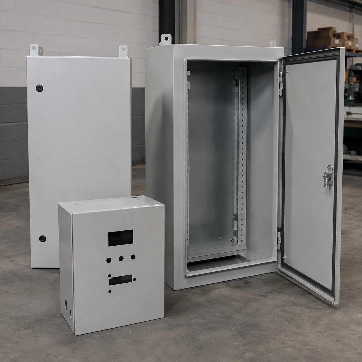
Sheet metal enclosures protect electronics, controls, sensors, power systems, and mechanical assemblies. A successful enclosure must do more than match an external shape. It needs manufacturable bends, accessible hardware, suitable ventilation, reliable grounding, practical finishing, and enough tolerance for assembly.
This guide explains the design details that have the greatest effect on cost and quality. It is intended for engineers and product designers preparing prototypes or low-volume production through sheet metal fabrication.
Start with Material and Sheet Thickness
Material selection affects strength, weight, corrosion, conductivity, appearance, and bendability. Aluminum is lightweight and corrosion resistant, making it common for electronics and portable equipment. Mild steel offers stiffness and economical material cost. Stainless steel is useful for washdown, outdoor, food, medical, and harsh environments but requires more forming force and may show tooling marks.
Sheet thickness should be chosen around panel size, load, fastening method, and bend geometry. Increasing thickness improves stiffness but adds weight and may require larger bend radii. Thin panels can be strengthened with flanges, beads, ribs, hems, or internal brackets instead of using uniformly thick material.
Design Bends with Realistic Radii
Every bend stretches and compresses the material. The inside bend radius should match the material, thickness, grain direction, tooling, and required appearance. A common starting point is an inside radius close to the sheet thickness, but the final value depends on the fabrication process.
Using one standard bend radius across the enclosure reduces tooling changes and simplifies programming. Very small radii increase cracking risk, especially in hard aluminum or stainless steel. Large radii may change the outside dimensions and flange length, so the flat pattern must account for bend allowance or bend deduction.
Keep Holes and Cutouts Away from Bend Zones
Features too close to a bend can stretch or distort during forming. Holes may become oval, slots may open, and edges may pull. The required distance depends on feature size, bend radius, and material thickness. When a hole must be close to a bend, a relief or post-bend machining operation may be necessary.
Bend reliefs prevent tearing where two bend lines meet. Relief shape can be rectangular, obround, or tear-shaped. The design should avoid narrow tabs that deform during bending or finishing.
Plan the Enclosure Around the Bend Sequence
A CAD model may appear valid but still be impossible to form because one flange blocks the tooling needed for the next bend. Deep boxes, inward flanges, and closely spaced bends are common sources of interference. The manufacturer may need staged tooling, segmented punches, or separate welded pieces.
During DFM review, consider whether the enclosure can be made as one folded part or should be divided into a base, cover, and internal brackets. More pieces add hardware or welding, but they may reduce tool complexity and improve access.
Select Hardware for Assembly and Service
Sheet metal often needs captive hardware because the sheet is too thin for durable threads. PEM-style nuts, studs, standoffs, rivet nuts, weld nuts, and threaded inserts can provide reliable attachment. Hardware selection should consider sheet thickness, installation direction, edge distance, torque, electrical grounding, and finish.
Inserted hardware is usually installed before powder coating or painting, but the sequence depends on the hardware and appearance requirements. Masking may be required to keep threads clean. If the enclosure will be serviced repeatedly, choose hardware that resists stripping and supports the expected number of assembly cycles.
Control Gaps, Fits, and Stack-Up
Sheet metal dimensions are influenced by material thickness, bend angle, bend radius, and springback. A cover that fits perfectly in CAD may bind if all tolerances accumulate in the same direction. Use practical clearances between mating parts, especially for long seams and removable covers.
Locate parts using tabs, slots, pilots, or formed features rather than relying only on loose fasteners. Critical interfaces should reference clear datums. Avoid applying tight tolerances to every bend; focus on hole patterns, mounting faces, latch locations, and interfaces with electronics or seals.
Ventilation, Sealing, and Cable Entry
Electronics enclosures may need louvers, perforations, fan cutouts, filters, or heat-sink interfaces. Vent openings should preserve stiffness and meet safety requirements. Large perforated areas may cause distortion during forming or finishing.
Sealed enclosures need consistent flange surfaces, gasket compression, corner details, and suitable fastener spacing. Cable glands and connectors need enough wrench clearance and should not interfere with internal components. If electromagnetic shielding is required, coating and grounding surfaces must be considered early.
Finish Selection
Powder coating provides durable color and corrosion protection for steel and aluminum. Anodizing is common for aluminum panels and housings. Passivation may be specified for stainless steel. Brushed or bead-blasted finishes can improve appearance but may reveal differences between welded and unwelded areas.
Finish thickness affects holes, tabs, sliding joints, and grounding. Mark surfaces that must remain bare. Cosmetic requirements should identify the visible side, acceptable grain direction, and areas where rack or contact marks are allowed.
Welding and Joint Design
Welding can create strong, sealed assemblies, but heat may distort thin panels. Short intermittent welds, balanced sequences, fixtures, and tabs can help control movement. Continuous welds should be used only when sealing or strength requires them.
For prototypes, screws and rivets may be faster and easier to revise. For production, spot welding, clinching, or dedicated fixtures may improve efficiency. The joint method should be selected around load, appearance, service, and volume.
Assembly Checks Before Release
- Confirm all bends can be reached in a practical sequence.
- Check hardware against sheet thickness and installation direction.
- Verify clearance for tools, connectors, cables, fans, and fasteners.
- Review cover gaps and tolerance stack-up.
- Identify cosmetic faces and grain direction.
- Confirm finish masking, grounding, and thread protection.
- Use an exploded view to verify assembly order.
- Test a prototype with real internal components before production.
Prepare a Complete Sheet Metal RFQ
Submit the 3D model, flat pattern if available, dimensioned drawing, material, thickness, finish, hardware list, weld notes, quantity, and inspection requirements. If several parts form an assembly, include a simple assembly drawing and photos of the internal components when useful.
RapidMfgPro can review enclosure geometry, bend feasibility, hardware, finish, and assembly risks before production. A focused DFM review helps turn a visually complete CAD model into a part that can be fabricated, finished, and assembled consistently.
Need Help Reviewing a Custom Part?
Share your CAD file and requirements to request supplier matching. Supplier capability and commercial terms must be verified before order placement.
Request Supplier Match