Time to read: 8 min
Tin, Nickel, or Silver Plating: Which Conductive Finish Is Best for Copper CNC Parts?
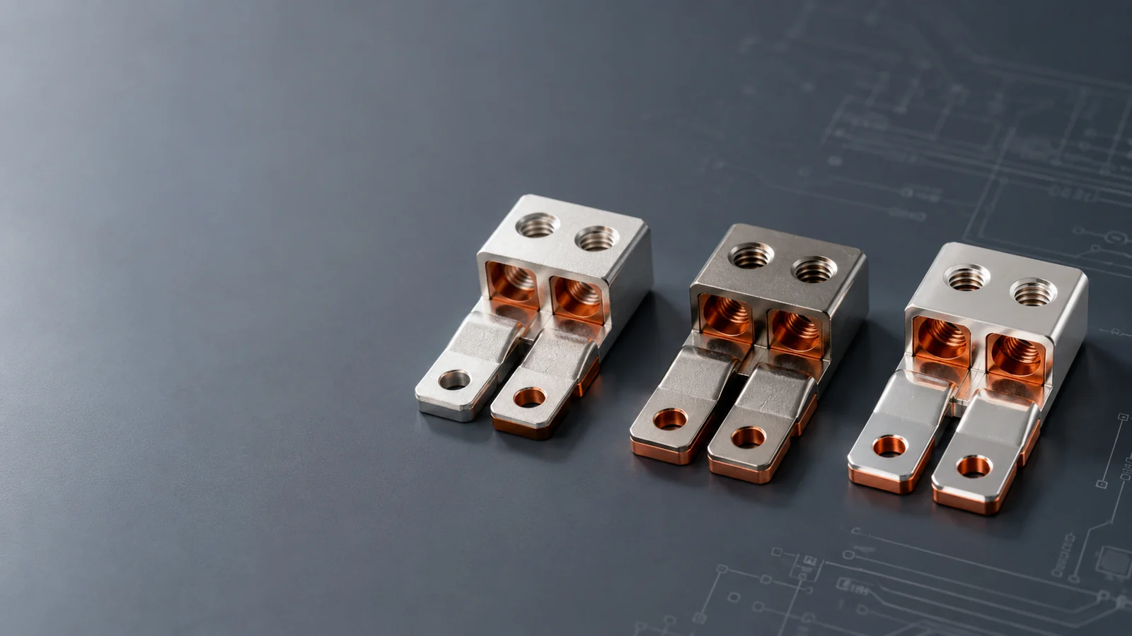
Tin, nickel, and silver are all used as conductive finishes on copper CNC parts, but they are selected for different electrical and mechanical reasons. Tin is commonly chosen for solderability, economical corrosion protection, and general electrical terminals. Nickel is usually chosen for hardness, wear, diffusion control, and barrier protection rather than maximum conductivity. Silver is selected when low contact resistance, high current capacity, heat transfer, or high-temperature electrical performance justifies its higher cost and tarnish-control requirements.
The best conductive finish cannot be selected from conductivity alone. A busbar joint, soldered terminal, sliding contact, RF enclosure, battery connector, heat spreader, and fluid-cooled copper part all place different demands on the plated surface. Contact force, current density, mating metal, fretting, temperature, humidity, sulfur exposure, soldering process, cleaning, thickness, porosity, and assembly cycle all influence the result.
The copper substrate also matters. C10100 oxygen-free copper, C11000 electrolytic tough-pitch copper, tellurium copper, brass, bronze, and beryllium-copper alloys do not have the same conductivity, machining behavior, surface chemistry, or heat-treatment limitations. A finish proven on pure copper should not be transferred automatically to every copper alloy.
RapidMFGPro evaluates plated copper projects from a supplier-matching perspective. The review considers the base alloy, current or signal requirement, soldering process, contact mechanics, underplate, final plating, thickness, selective areas, masking, post-treatment, inspection, documentation, quantity, and packaging before identifying suppliers whose machining and plating capabilities fit the actual part.
This guide compares tin, nickel, and silver plating for copper CNC parts and explains how engineers and buyers can select the most suitable conductive finish for each application.
Which Conductive Finish Is Best?
Tin is usually the best starting point for soldered electrical parts and cost-sensitive terminals. Nickel is usually the best starting point for wear, diffusion control, and hard barrier layers. Silver is usually the best starting point for high-current and low-contact-resistance applications.
Choose Tin for Solderability
Tin wets readily with common solder systems and protects copper from oxidation during storage and assembly. It is widely used on terminals, busbars, connector tabs, shielding parts, and copper components that will be soldered.
Tin is softer than nickel and silver and can deform under contact pressure. Pure-tin systems also require consideration of whisker growth, fretting, and temperature.
Choose Nickel for Wear and Barrier Protection
Nickel provides a harder surface and is frequently used as an underplate beneath tin, silver, or gold. It reduces copper diffusion, improves wear resistance, and creates a more stable base for additional finishes.
Nickel has higher electrical resistance than copper or silver, so it is not always the preferred exposed surface for high-current contact.
Choose Silver for High Current
Silver provides extremely high electrical and thermal conductivity and maintains low contact resistance under suitable contact pressure.
It is commonly used for high-current busbars, switchgear, power contacts, battery systems, RF components, and high-temperature electrical joints.
| Part Requirement | Recommended Starting Finish | Main Reason |
|---|---|---|
| Soldered copper terminal | Tin plating | Economical solderability and oxidation protection |
| High-current busbar joint | Silver plating | Low contact resistance and strong current performance |
| Sliding electrical contact | Nickel underplate with selected topcoat | Wear resistance and diffusion control |
| Hard corrosion-resistant copper component | Nickel plating | Hard barrier surface |
| Cost-sensitive connector tab | Tin plating | Low cost and broad process availability |
| Power switch contact | Silver plating | Low resistance and heat tolerance |
Start with the Electrical Function
Conductive-finish selection should begin with how electricity passes through the part rather than the visual appearance of the coating.
Bulk Conductivity
Bulk conductivity describes current flow through the copper body. A thin surface coating normally has limited influence on the resistance of a thick copper section.
The copper grade, cross-sectional area, length, temperature, and internal defects control most of the bulk resistance.
Surface Contact Conductivity
Surface contact conductivity describes how current passes across a joint, connector, fastener, spring, brush, or mating face.
Oxide, tarnish, roughness, contact force, contamination, and coating hardness can dominate the joint resistance.
Soldered Conductivity
A soldered joint depends on wetting, intermetallic formation, flux, heat, cleanliness, and final joint geometry.
The most conductive finish is not automatically the easiest finish to solder.
Signal Contact
Low-level signal contacts require stable resistance under low contact force.
Oxide and fretting behavior may matter more than bulk conductivity.
What Is Tin Plating?
Tin plating deposits a thin tin or tin-alloy layer onto copper or copper alloy. It is widely used because it combines solderability, corrosion protection, electrical function, and reasonable cost.
Electroplated Tin
Electroplated tin is deposited using electrical current. It can be applied selectively or over the entire part.
Thickness distribution depends on current density, part geometry, rack design, and bath chemistry.
Matte Tin
Matte tin has a lower-brightener deposit structure and is commonly used for solderable electronic and electrical components.
It is often selected when whisker-control and soldering reliability are important.
Bright Tin
Bright tin provides a reflective appearance and smooth visual finish.
Organic brighteners affect deposit stress, solderability, and aging behavior.
Reflowed Tin
Reflow heating melts the tin surface and produces a smoother, more stable finish.
The thermal cycle can affect the copper substrate, underplate, dimensions, and nearby assembly materials.
What Is Nickel Plating?
Nickel plating creates a hard, corrosion-resistant, metallic layer on copper. Nickel may be applied electrolytically or by an electroless process.
Electrolytic Nickel
Electrolytic nickel is deposited using electrical current.
It is widely used as an underplate and can provide bright, semi-bright, satin, or engineering finishes.
Electroless Nickel
Electroless nickel uses an autocatalytic chemical process and provides more uniform thickness on complex geometry.
Nickel-phosphorus content changes conductivity, hardness, magnetism, and corrosion performance.
Nickel as an Underplate
Nickel is commonly placed between copper and tin, silver, or gold.
The layer limits copper diffusion, supports the topcoat, and improves wear resistance.
Nickel as a Final Finish
Exposed nickel is used where hardness, corrosion resistance, solderability in selected systems, and metallic appearance matter more than minimum contact resistance.
Oxide and higher electrical resistance can limit its use on low-force power contacts.
What Is Silver Plating?
Silver plating deposits a conductive silver layer onto copper, copper alloy, or a nickel underplate. It is one of the most important finishes for high-current electrical parts.
Electroplated Silver
Silver is usually deposited electrochemically and may be applied over the complete part or only the contact region.
Thickness and hardness are selected according to current, wear, mating cycles, and service environment.
Soft Silver
Soft silver provides high conductivity and conforms under contact pressure.
It is used on bolted busbar joints and stationary high-current contacts.
Hard Silver
Hard silver contains controlled alloying additions or deposit structures that improve wear resistance.
Conductivity may be lower than pure soft silver.
Silver over Nickel
A nickel underplate limits copper migration and creates a harder support layer.
The complete stack should be selected according to temperature, contact force, and corrosion exposure.
How Does Electrical Conductivity Compare?
Silver has the highest electrical conductivity of the three finishes. Tin and nickel are less conductive, but surface condition and contact design can outweigh the theoretical material value.
Silver Conductivity
Silver provides very low electrical resistance and is preferred for high-current and high-performance contacts.
Tarnish, wear, porosity, and contact force must still be controlled.
Tin Conductivity
Tin is sufficiently conductive for many terminals, connectors, and soldered joints.
Oxide films and fretting can increase resistance in low-force contacts.
Nickel Conductivity
Nickel is conductive but has significantly higher resistivity than copper and silver.
It is more valuable as a barrier and wear layer than as the lowest-resistance contact finish.
Contact Geometry
Real electrical contact occurs through small microscopic areas where surface peaks touch.
Contact force, flatness, roughness, hardness, and oxide determine the effective conductive area.
| Selection Factor | Tin Plating | Nickel Plating | Silver Plating |
|---|---|---|---|
| Electrical conductivity | Moderate | Lower than tin and silver | Highest |
| Solderability | Excellent | Conditional | Good with process control |
| Wear resistance | Low to moderate | High | Moderate; higher with hard silver |
| Main environmental risk | Oxide, fretting, and whiskers | Oxide and higher contact resistance | Sulfur tarnish and migration |
| Typical role | Solderable final finish | Barrier or wear underplate | High-current final contact |
| Relative cost | Low | Moderate | High |
How Does Contact Resistance Compare?
Contact resistance depends on the coating surface after storage and service, not only the conductivity of the clean plating metal.
Tin Contact Resistance
Tin oxide is stable and can increase contact resistance under low force.
Tin contacts often rely on wiping action, higher contact pressure, or soldered joints.
Nickel Contact Resistance
Nickel oxide is harder and can create unstable resistance in low-force signal contacts.
Nickel is therefore commonly covered by gold, silver, or tin when stable low resistance is required.
Silver Contact Resistance
Silver sulfide tarnish can form in sulfur-containing environments.
Sufficient contact force can break through thin tarnish on many power contacts.
Contact Pressure
Soft finishes deform and increase real contact area.
Hard underplates prevent excessive wear but may reduce conformability if the topcoat is too thin.
Which Finish Is Best for Soldering?
Tin is generally the preferred solderable finish for copper CNC parts. Silver and nickel can also be soldered, but their process windows and aging behavior differ.
Tin Solderability
Tin dissolves and reacts readily with common solders.
Storage, oxidation, underplate, thickness, and reflow exposure influence wetting.
Silver Solderability
Silver-plated copper can solder well and is used in high-temperature, RF, and power applications.
Silver dissolution into molten solder and tarnish should be considered.
Nickel Solderability
Fresh nickel can be soldered with suitable flux and process control.
Nickel oxide makes soldering more difficult than tin, especially after long storage.
Underplate Function
Nickel under tin or silver limits copper-tin and copper-silver diffusion during storage and heat exposure.
Underplate thickness should match the soldering temperature and product life.
What Is Tin Whisker Risk?
Tin whiskers are fine metallic filaments that can grow from tin-plated surfaces and create electrical shorts in closely spaced electronics.
Pure-Tin Deposits
Pure tin can develop whiskers under residual stress, intermetallic growth, temperature cycling, and environmental exposure.
The exact mechanism is complex and cannot be eliminated by one control alone.
Nickel Underplate
Nickel under tin can reduce copper diffusion and change intermetallic growth.
It is one part of a broader whisker-mitigation strategy.
Matte Tin
Matte tin is commonly preferred over highly stressed bright tin for whisker-sensitive applications.
Deposit stress and process control remain important.
Alternative Finishes
Tin alloys, nickel, silver, gold, conformal coating, spacing, and electrical design may be considered.
Regulatory restrictions can limit lead-containing tin alloys.
What Is Silver Tarnish?
Silver tarnish is commonly associated with sulfur compounds reacting with the silver surface and forming a dark silver-sulfide layer.
Sulfur Exposure
Rubber, cardboard, paper, industrial air, fuels, packaging materials, and process chemicals can release sulfur-containing compounds.
Storage and packaging therefore influence silver appearance and contact behavior.
Electrical Effect
Thin tarnish may be penetrated by high contact force.
Low-force signal contacts are more sensitive to surface films.
Anti-Tarnish Treatment
Organic or chemical anti-tarnish treatments slow discoloration.
The treatment may affect contact resistance, solderability, bonding, or cleaning.
Packaging Control
Sulfur-free papers, films, trays, and desiccants can reduce tarnish risk.
The packaging specification should be included in the project.
What Is Nickel Oxidation?
Nickel forms an oxide film that protects the surface from corrosion but can interfere with soldering and low-force electrical contact.
Barrier Benefit
Nickel oxide contributes to corrosion resistance and slows further metal reaction.
This is valuable for structural and wear surfaces.
Contact Limitation
The oxide is less conductive than metallic nickel.
Stable signal contacts usually use a noble or softer top finish.
Soldering Limitation
Aged nickel surfaces need stronger flux and tighter process control than fresh tin.
Storage time and cleanliness should be defined.
How Does Wear Resistance Compare?
Nickel provides the strongest hardness and wear foundation. Tin is soft, while silver performance depends strongly on deposit hardness and contact design.
Tin Wear
Tin can smear, transfer, and wear through under repeated sliding.
It is better for soldered, stationary, or limited-cycle contacts than high-cycle wiping interfaces.
Nickel Wear
Nickel resists abrasion and provides a hard support layer beneath softer topcoats.
Exposed nickel can increase mating-part wear.
Silver Wear
Soft silver conforms well but wears under sliding. Hard silver extends cycle life.
Contact lubrication and pressure influence transfer and galling.
Multilayer Contact Systems
Nickel underplate with silver or gold topcoat combines support with low contact resistance.
Thickness should reflect the expected number of mating cycles.
How Does Corrosion Resistance Compare?
Tin, nickel, and silver protect copper differently. Porosity, underplate, thickness, environment, and galvanic contact control the final result.
Tin Corrosion Behavior
Tin protects copper from oxidation in many indoor and mild environments.
Porous tin can allow local copper corrosion and discoloration.
Nickel Corrosion Behavior
Nickel provides a hard barrier and can protect copper from moisture, handling, and selected chemicals.
Pores and cracks can create localized galvanic attack at exposed copper.
Silver Corrosion Behavior
Silver does not form the same insulating oxide as copper, but sulfur tarnish is a major concern.
Exposed copper through porous silver can corrode and stain the surface.
Underplate Protection
Nickel under silver or tin reduces copper exposure and diffusion.
The stack should be selected for humidity, temperature, sulfur, salt, and chemical service.
How Does Temperature Affect the Finish?
Temperature changes conductivity, diffusion, oxidation, solderability, coating stress, and contact performance.
Tin at Elevated Temperature
Tin softens and can creep under contact pressure.
Copper-tin intermetallic layers grow faster as temperature increases.
Nickel at Elevated Temperature
Nickel provides a stable barrier and retains hardness better than tin.
Oxidation and magnetic behavior should still be considered.
Silver at Elevated Temperature
Silver maintains strong conductivity and is used in high-temperature electrical contacts.
Creep, diffusion, wear, and mating-material compatibility remain important.
Thermal Cycling
Repeated temperature changes stress the coating stack because copper, nickel, tin, and silver expand differently.
Adhesion and thickness should be validated through cycling when required.
Which Finish Is Best for High Current?
Silver is generally the best finish for high-current contact surfaces because it combines low resistance, good thermal conductivity, and useful high-temperature performance.
Busbar Joints
Silver-plated busbar pads reduce joint resistance and heating when clamping force is controlled.
Flatness, roughness, bolt preload, washer design, and contamination are as important as plating.
Switchgear Contacts
Silver and silver-alloy contacts are used in breakers, switches, relays, and disconnects.
Arc erosion and contact welding may require specialized silver alloys rather than pure silver plating.
Battery Connections
Silver is used for demanding battery terminals and bus structures where resistance and heat are tightly controlled.
Tin remains common for lower-cost battery hardware and soldered assemblies.
Nickel Barrier
Nickel under silver limits copper diffusion and supports wear.
Excessive nickel thickness can add resistance to thin or small-current paths.
Which Finish Is Best for Low-Level Signals?
Tin, nickel, and silver can all create problems in very low-force signal contacts because their surface films and fretting behavior differ.
Tin Signal Contacts
Tin can work when contact force and wiping action break the oxide.
Fretting corrosion is a known risk under vibration and small repeated motion.
Nickel Signal Contacts
Exposed nickel oxide creates high and unstable resistance under low force.
Nickel is more commonly used under gold for signal connectors.
Silver Signal Contacts
Silver provides low resistance but tarnish can affect low-force contacts.
Clean environments, higher contact force, or protective systems may be required.
Gold Alternative
Gold over nickel is commonly preferred for low-level, low-force, high-reliability signal contacts.
Tin, nickel, and silver remain important for power, soldering, and cost-controlled applications.
Which Finish Is Best for RF Parts?
RF parts require consideration of surface conductivity, skin effect, roughness, magnetic behavior, shielding continuity, and frequency.
Silver for RF Conductivity
Silver is widely used on waveguides, filters, resonators, contacts, and RF housings because current flows near the surface at high frequency.
Thickness, roughness, tarnish, and seam contact affect loss.
Nickel Magnetic Behavior
Nickel can increase RF loss in applications sensitive to magnetic permeability.
The underplate should be reviewed rather than specified automatically.
Tin for Shielding Assemblies
Tin-plated copper and brass are used for solderable EMI shields, seams, and enclosure components.
Contact design and oxide penetration determine shielding continuity.
Surface Roughness
Roughness increases effective RF path length and can raise loss.
Machining and plating should produce the required final surface.
Which Finish Is Best for Thermal Parts?
Copper thermal parts are selected primarily for bulk conductivity, but the surface finish affects contact, soldering, oxidation, and radiative behavior.
Silver Thermal Interfaces
Silver offers high thermal conductivity and conforms under pressure.
It is used in premium electrical and thermal interfaces where cost is justified.
Tin-Soldered Cold Plates
Tin plating supports soldering of copper cold plates, tubes, and heat exchangers.
The plating and solder process should be compatible with internal cleanliness and joint temperature.
Nickel Barrier Coatings
Nickel protects copper cold plates and heat spreaders from oxidation and fluid exposure.
The thin coating usually has limited effect on bulk heat flow but can affect interface resistance.
Which Copper Grades Are Commonly Plated?
Pure copper and copper alloys are plated for different reasons. Grade selection affects conductivity, machining, pretreatment, hardness, and heat response.
C10100 Copper
C10100 oxygen-free copper provides very high conductivity and low oxygen content.
It is used for vacuum, RF, electronics, and high-performance power parts.
C11000 Copper
C11000 is widely used for busbars, terminals, electrical plates, and machined power components.
Tin, nickel, and silver are all common finishes.
Tellurium Copper
Tellurium copper provides better machinability than pure copper while retaining useful conductivity.
Surface chemistry and alloy inclusions should be considered during pretreatment.
Brass and Bronze
Brass and bronze components are plated for solderability, appearance, wear, corrosion, and electrical contact.
Leaded phases, zinc content, and surface activation affect adhesion.
Beryllium Copper
Beryllium copper is used for springs, contacts, and high-cycle electrical components.
Plating sequence must be coordinated with aging heat treatment and worker-safety controls.
How Does Copper Pretreatment Work?
Copper plating adhesion depends on complete cleaning, oxide removal, activation, and controlled transfer into the plating bath.
Degreasing
Cutting oil, coolant, polishing compound, fingerprints, wax, and silicone are removed.
Poor cleaning creates skips, blisters, pits, and poor solderability.
Oxide Removal
Copper oxide and tarnish are chemically removed without excessive attack on the base metal.
Aggressive cleaning can change dimensions and roughness.
Acid Activation
A final activation step creates a chemically active surface immediately before plating.
Delays allow oxide to reform.
Strike Layers
Selected alloys or coating stacks use a thin strike layer to improve adhesion.
The strike chemistry should be compatible with the final finish and service.
Why Is Nickel Used as an Underplate?
Nickel underplate performs several functions that cannot be achieved by simply increasing the topcoat thickness.
Copper-Diffusion Barrier
Copper atoms migrate into tin, silver, and gold over time and at elevated temperature.
Nickel slows diffusion and reduces surface discoloration and intermetallic growth.
Hard Support Layer
Nickel supports soft tin, silver, or gold during mating and wear.
It helps prevent the contact from reaching the copper substrate quickly.
Porosity Reduction
A continuous nickel layer covers copper machining texture and reduces direct copper exposure through the topcoat.
Underplate quality still depends on pretreatment and thickness.
Adhesion Foundation
Nickel provides a consistent base for noble-metal plating.
Excessively stressed or poorly activated nickel can cause peeling of the complete stack.
When Is a Copper Underplate Used?
A copper underplate can improve leveling, adhesion, thickness buildup, and compatibility on selected substrates, but it is not always needed on a copper part.
Leveling Layer
Ductile copper plating can fill minor roughness before nickel or decorative topcoats.
It does not repair deep pits or dimensional defects economically.
Repair Buildup
Thick copper can restore worn dimensions before nickel or silver finishing.
Final machining and remaining thickness should be controlled.
Adhesion Layer
Copper strikes are used on selected alloys and non-copper substrates.
On pure copper CNC parts, direct nickel, tin, or silver plating may be possible after activation.
How Should Plating Thickness Be Selected?
Thickness should be based on function, porosity, wear life, diffusion, corrosion, soldering, and dimensional tolerance.
Thin Tin
Thin tin is used for solderability and mild oxidation protection.
Very thin deposits may wear through quickly and expose copper.
Thick Tin
Thicker tin improves coverage and wear allowance.
It increases dimensional change, material use, and whisker-related stress considerations.
Nickel Underplate Thickness
Nickel must be thick enough to provide a continuous barrier and support layer.
Excess thickness increases cost and electrical resistance.
Silver Thickness
Stationary busbar joints may use a thinner conductive layer than high-cycle sliding contacts.
Wear, current density, porosity, and service life determine the final range.
| Coating Function | Thickness Tendency | Main Risk if Too Thin | Main Risk if Too Thick |
|---|---|---|---|
| Tin solderability | Thin to moderate | Copper exposure and poor storage life | Dimensional buildup and deposit stress |
| Nickel diffusion barrier | Moderate and continuous | Copper migration through pores | Higher resistance and cost |
| Silver stationary contact | Moderate | Porosity and early wear-through | Cost and dimensional buildup |
| Silver sliding contact | Moderate to thick | Short mating-cycle life | Cost and soft-metal deformation |
| Nickel wear surface | Moderate to thick | Early substrate exposure | Stress and cracking risk |
How Does Plating Change Dimensions?
Tin, nickel, and silver all add material outward from the copper surface. Every plated side must be included in the dimensional calculation.
External Dimensions
Shafts, bosses, pads, and external threads increase in size.
Multilayer stacks add the thickness of each deposit.
Internal Dimensions
Holes, slots, grooves, and internal threads become smaller.
Thickness may vary in deep recesses during electroplating.
Contact Flatness
Plating follows the substrate and does not automatically correct warped or uneven copper pads.
High-current contact faces may require post-plate lapping or controlled polishing.
Final Tolerance
Critical dimensions should be inspected after all plating and heat treatments.
The drawing should state whether dimensions apply before or after finish.
How Should Selective Plating Be Used?
Selective plating places the expensive or function-specific finish only where it is needed.
Contact Pads
Silver can be limited to bolted busbar pads or switch-contact areas.
The rest of the copper may remain bare, tin plated, nickel plated, or protected by another coating.
Soldering Areas
Tin can be applied only to solder tails, tabs, or wire-termination zones.
Mechanical interfaces can use a harder or different finish.
Wear Areas
Nickel can be applied to bearing, sliding, or mating regions while conductive faces receive silver or tin.
Transitions should be placed outside high-stress and high-current zones.
Cost Control
Selective silver plating reduces precious-metal consumption.
Masking and tooling cost should be compared with material savings.
How Should Masking Be Specified?
Masking controls plated and unplated areas, prevents thread interference, and separates different coating systems.
Dimensioned Boundaries
Coating boundaries should be shown by dimensions, section views, or identified model surfaces.
A note such as plate contact area is not sufficiently precise.
Thread Masking
Fine threads, press fits, and grounding features may require plugs, caps, tape, lacquer, or custom tooling.
The final thread condition should be gauged.
Transition Zones
Plating boundaries have a finite transition rather than a perfectly sharp line.
The drawing should define the acceptable width and appearance.
Rack Contact Areas
Electroplating requires electrical contact to the part.
Rack marks should be located outside critical cosmetic, sealing, or conductive surfaces.
How Do Threads Behave after Plating?
Plating changes thread dimensions, friction, solder contamination risk, and electrical contact.
Tin-Plated Threads
Soft tin can smear and transfer during assembly.
It can support low-resistance bolted joints but may alter torque and preload.
Nickel-Plated Threads
Nickel provides a harder thread surface and reduces galling on selected material pairs.
Fine threads require allowance for buildup.
Silver-Plated Threads
Silver plating can reduce galling and improve conductivity in high-temperature threaded joints.
Soft silver may extrude under excessive torque.
Final Gauging
Go/No-Go gauges should be used after the final plating stack.
Assembly torque should be validated with the finished surface.
How Do Press Fits Behave after Plating?
Plating affects interference, insertion force, coating damage, and electrical continuity.
Soft Topcoats
Tin and soft silver can shear, smear, or cold flow during press fitting.
Removed metal may contaminate the assembly.
Nickel Support
Nickel provides a harder surface and better wear support.
It can crack if the interference is excessive or the substrate deforms.
Masked Fits
Precision bores and shafts may be masked and assembled as bare copper.
Exposed copper then requires oxidation and galvanic review.
How Does Surface Roughness Affect Performance?
Plating follows the copper surface. Machining marks, scratches, burrs, pits, and waviness affect contact, soldering, wear, and appearance.
Electrical Contact Faces
Very rough faces create high local pressure and limited real contact area.
Controlled flatness and roughness reduce joint heating.
Soldering Surfaces
Excessive roughness traps flux and contamination.
A moderately clean surface supports uniform solder wetting.
Wear Surfaces
Rough nickel or silver accelerates abrasive wear on the mating contact.
Polishing and controlled deposit structure improve cycle life.
Cosmetic Surfaces
Bright nickel and silver reveal dents, scratches, and polishing variation.
Cosmetic acceptance should begin with the machined copper surface.
How Should Edges Be Designed?
Sharp edges create current-density concentration, thin mechanical support, burrs, and early coating wear.
Sharp External Edges
Electroplating can build more rapidly at high-current-density edges.
The soft coating can then be damaged during handling.
Internal Corners
Deep internal corners receive less current and may have thinner tin, nickel, or silver.
Radii improve plating access and stress distribution.
Burr Removal
Copper burrs become plated and can remain sharp or break off.
Parts should be fully deburred before finishing.
Contact Edge Location
High-current contact should occur on supported faces rather than knife edges.
Broad pads reduce local heating and coating damage.
How Do Blind Holes and Passages Affect Plating?
Electroplating is sensitive to current distribution and solution exchange in deep or shielded features.
Blind Holes
Deep blind holes can receive thinner electroplated tin, nickel, or silver.
Trapped gas and solution reduce coverage.
Internal Threads
Thread roots may receive less deposit than exposed crests.
Plugging or alternative plating methods may be required.
Fluid Passages
Copper cold plates and manifolds can trap plating solution and rinse water.
Drainage, flushing, and cleanliness inspection are essential.
Electroless Nickel Alternative
Electroless nickel can provide more uniform internal coverage than electrolytic nickel.
Tin and silver topcoats may still require line-of-sight current distribution.
How Are CNC-Milled Copper Parts Plated?
Milled copper housings, busbars, heat spreaders, manifolds, electrodes, and RF components often combine broad faces with recesses and precision features.
Busbar Pads
Contact pads require controlled flatness, roughness, plating thickness, and masking boundaries.
Selective silver or tin is common.
Deep Pockets
Electroplated thickness decreases in shielded pockets.
Auxiliary anodes, tooling, or electroless nickel may improve coverage.
Cooling Channels
Internal passages need complete cleaning and verified coating where required.
Residual chemistry can contaminate cooling fluid.
Large Flat Faces
Broad cosmetic faces reveal pits, stains, burns, and handling marks.
Rack design and current distribution should be reviewed.
How Are CNC-Turned Copper Parts Plated?
Turned copper connectors, contacts, pins, sleeves, electrodes, terminals, and threaded parts are sensitive to concentric buildup and thread fit.
Contact Pins
Tin supports soldering, nickel supports wear, and silver supports high-current contact.
Gold may be preferred for low-level signal pins.
Connector Sleeves
Internal and external diameters need plating allowance.
Thickness distribution should preserve concentricity.
Electrodes
Nickel can provide wear and oxidation resistance on selected copper electrodes.
The coating may alter electrical discharge or thermal behavior.
Threaded Terminals
Tin or silver can improve electrical joints.
Torque, contact pressure, and coating extrusion should be validated.
Which Finish Is Best for Copper Busbars?
Tin and silver are the most common finishes for copper busbars. Nickel is typically used as a barrier or specialized final surface.
Tin-Plated Busbars
Tin is economical and protects copper from oxidation in electrical cabinets, battery packs, power distribution units, and industrial equipment.
It is suitable for many bolted and soldered connections.
Silver-Plated Busbars
Silver is selected for higher current density, elevated temperature, lower joint resistance, and demanding switchgear or power applications.
Tarnish and cost require control.
Nickel-Plated Busbars
Nickel is used in high-temperature, corrosion, battery-welding, and barrier applications.
Its higher electrical resistance must be included in joint design.
Selective Contact Plating
Silver or tin can be limited to bolt pads and contact zones.
The remaining busbar can be insulated, coated, or left bare according to the enclosure design.
Which Finish Is Best for Battery Parts?
Battery components require attention to conductivity, joining, corrosion, temperature, electrolyte, galvanic contact, and cell chemistry.
Tin for Soldered or Bolted Connections
Tin is used on copper tabs, busbars, terminals, and low-cost battery interconnects.
Welding and soldering process compatibility should be validated.
Nickel for Welding and Barrier Layers
Nickel-plated copper can support laser, resistance, and ultrasonic joining in selected battery designs.
Nickel thickness affects weld energy and electrical resistance.
Silver for Premium Power Contacts
Silver is used where low resistance and heat management justify the cost.
Electrolyte and sulfur exposure should be considered.
Galvanic Compatibility
Copper, aluminum, nickel, steel, and plated hardware can form galvanic couples.
Joint sealing and environmental control are important.
Which Finish Is Best for Connectors?
Connector finish depends on current, signal level, mating cycles, contact force, environment, and soldering.
Tin Connectors
Tin is common in automotive, appliance, industrial, and power connectors.
It requires sufficient normal force and wiping action to manage oxide and fretting.
Nickel Connectors
Nickel is commonly used under tin, silver, and gold.
Exposed nickel is more suitable for mechanical or high-force contacts than sensitive signals.
Silver Connectors
Silver is used for higher-current connectors, charging interfaces, and power contacts.
Hard silver and lubrication improve mating-cycle life.
Mixed-Finish Connectors
A connector can use tin solder tails, nickel underplate, and silver or gold mating surfaces.
Selective plating aligns each finish with its function.
Which Finish Is Best for Copper Heat Exchangers?
Copper heat exchangers, cold plates, evaporators, and cooling components may use tin, nickel, or silver for joining, corrosion, cleanliness, and interface performance.
Tin for Soldering
Tin supports soldered tube, plate, and fin assemblies.
Flux residue and internal cleanliness must be controlled.
Nickel for Fluid Resistance
Nickel protects copper from selected coolants, humidity, and handling.
The coating must remain continuous inside fluid-contact passages.
Silver for Brazing and High Conductivity
Silver-based joining and plating systems are used in specialized thermal assemblies.
Cost and galvanic behavior require review.
Thermal Interface Pads
Silver-plated copper pads can reduce oxidation at bolted thermal joints.
Flatness and contact pressure remain critical.
How Does Plating Affect Welding and Brazing?
Plating changes heat absorption, wetting, intermetallic formation, fumes, and joint chemistry.
Tin before Welding
Tin can contaminate fusion welds and alter laser or resistance-welding behavior.
Welding may be completed before tin plating or validated as a plated process.
Nickel before Welding
Nickel-plated copper is used in battery welding and other joining processes.
Thickness and energy settings should be controlled.
Silver before Brazing
Silver surfaces can support brazing and high-temperature joining.
The plating may dissolve into the filler metal.
Heat-Affected Coating
Heat can discolor, oxidize, diffuse, melt, or crack the plating around the joint.
Post-join cleaning or replating may be required.
How Does Plating Affect Crimping?
Crimping plastically deforms the terminal and coating around a wire or mating component.
Tin-Plated Crimps
Tin-plated copper terminals are widely used because tin supports corrosion protection and electrical contact.
Coating thickness should not interfere with strand compression.
Nickel-Plated Crimps
Nickel-plated copper is used in high-temperature and corrosion-sensitive harnesses.
Greater hardness requires validated crimp force and tooling.
Silver-Plated Crimps
Silver-plated conductors are used in aerospace, high-temperature, and high-current wiring.
Tarnish and storage should be controlled.
Crimp Inspection
Pull force, crimp height, cross-section, electrical resistance, and environmental testing may be required.
Visual appearance alone does not prove joint quality.
How Is the Plating Process Controlled?
A typical plating sequence includes cleaning, activation, underplating, final plating, rinsing, post-treatment, drying, and inspection.
Cleaning Control
Water-break testing, bath concentration, temperature, time, and part handling help confirm cleanliness.
Copper that appears visually clean may still carry organic residue.
Current-Density Control
Electroplated thickness and structure depend on current density.
Edges, recesses, shields, and rack contacts receive different current.
Bath Chemistry
Metal concentration, additives, contamination, pH, temperature, and agitation influence deposit quality.
Bath age and maintenance affect repeatability.
Rinsing Control
Poor rinsing leaves stains, salts, and trapped chemistry.
High-purity final rinse may be required for electronics and vacuum parts.
Drying and Handling
Water spots, fingerprints, sulfur exposure, and abrasion can damage the finish immediately after plating.
Clean gloves and controlled packaging are important.
What Tin-Plating Defects Commonly Occur?
Tin-plating problems can involve adhesion, oxidation, whiskers, discoloration, roughness, thickness, solderability, and fretting.
Blistering and Peeling
Poor cleaning, oxide, stressed underplate, or contaminated activation can cause adhesion failure.
The failure interface should be examined.
Whisker Growth
Residual stress and intermetallic growth can produce fine conductive filaments.
Material, underplate, deposit type, thickness, and environmental controls should be reviewed.
Poor Solderability
Oxidation, contamination, excessive intermetallic growth, and storage can reduce wetting.
Solderability testing should match the production process.
Fretting Corrosion
Small repeated motion breaks the tin surface and creates oxide debris.
Contact force, plating thickness, lubrication, and connector design affect resistance growth.
What Nickel-Plating Defects Commonly Occur?
Nickel defects commonly include peeling, pits, burns, high stress, cracks, porosity, roughness, and incomplete coverage.
Peeling
Copper oxide, delayed activation, contamination, or a poor strike causes weak adhesion.
Subsequent tin or silver can peel with the nickel beneath it.
High Deposit Stress
Bath chemistry and additives influence tensile or compressive stress.
Thick stressed nickel can crack or distort thin copper parts.
Pitting
Gas bubbles, particles, substrate defects, and bath contamination create pits.
Pits can penetrate the topcoat and expose copper.
Burned Edges
Excess current creates rough, dark, brittle deposit at sharp edges and rack-adjacent areas.
Current distribution and shielding should be controlled.
What Silver-Plating Defects Commonly Occur?
Silver-plating problems include tarnish, poor adhesion, porosity, discoloration, roughness, burns, migration, and wear.
Tarnish
Sulfur exposure darkens the surface.
Packaging and anti-tarnish treatment should be controlled.
Porosity
Thin or rough silver can contain pores that expose copper or nickel.
Corrosion products can appear through the topcoat.
Silver Migration
Under voltage and moisture, silver can migrate across insulating surfaces and create conductive paths.
Spacing, sealing, coating design, and environment should be reviewed.
Wear-Through
Sliding contacts can remove soft silver and expose nickel.
Hard silver, greater thickness, lubrication, or revised contact geometry may be required.
How Is Plating Thickness Inspected?
Thickness inspection should confirm each layer of the plating stack at locations that represent the critical electrical and mechanical surfaces.
X-Ray Fluorescence
X-ray fluorescence can measure tin, nickel, silver, and multilayer stacks without cutting the part.
Geometry, calibration standards, and spot size influence accuracy.
Cross-Section Measurement
A mounted and polished cross-section reveals individual layers, porosity, and interface condition.
The method is destructive and should use representative samples or coupons.
Coulometric Testing
Coulometric methods dissolve the coating electrochemically and calculate thickness.
They are useful for selected metal stacks and flat areas.
Measurement Location
Thickness at an exposed edge may not represent a recessed contact.
The drawing should identify critical measurement points.
How Is Adhesion Inspected?
Adhesion testing checks whether the coating stack remains bonded during bending, heating, impact, assembly, and service.
Bend Testing
Thin coupons or selected parts are bent to reveal cracking or peeling.
Hard nickel and thick deposits require interpretation because the substrate itself may deform.
Thermal Shock
Heating and rapid cooling create expansion mismatch between copper and the plated layers.
Blistering indicates weak adhesion or trapped contamination.
Burnishing
A smooth tool rubs the surface and checks for blistering or lifting.
This method is more suitable for selected geometries and coating thicknesses.
Functional Assembly
Press fitting, thread assembly, crimping, and mating cycles can expose adhesion weakness.
Functional tests should supplement coupon tests when failure risk is high.
How Is Electrical Performance Inspected?
Electrical testing should represent the final joint, contact force, current, temperature, and environmental state.
Bulk Resistance
Four-wire measurement can evaluate copper-part resistance without excessive lead error.
Cross-section, length, temperature, and alloy should be recorded.
Contact Resistance
Contact resistance is measured across the plated joint under a defined force.
Surface cleanliness and mating history affect the reading.
Temperature-Rise Testing
High current is passed through the assembly while temperature increase is monitored.
This directly evaluates electrical and thermal performance.
Environmental Aging
Humidity, temperature cycling, sulfur exposure, vibration, and mating cycles can be followed by resistance testing.
Initial low resistance alone does not prove long-term stability.
How Is Solderability Inspected?
Solderability testing should use the actual solder alloy, flux, temperature, storage condition, and assembly method.
Dip-and-Look Testing
The plated sample is fluxed and dipped into molten solder.
Coverage and wetting are evaluated visually.
Wetting-Balance Testing
A wetting balance measures the force and time associated with solder wetting.
It provides quantitative comparison between fresh and aged finishes.
Steam Aging
Accelerated aging exposes the coating to moisture and heat before solderability testing.
It helps reveal storage sensitivity.
Production Trial
Real components should be soldered using the intended equipment and thermal profile.
Joint voiding, intermetallic thickness, and residue may require inspection.
How Should Plated Copper Parts Be Packaged?
Packaging should prevent scratches, sulfur tarnish, fingerprints, humidity, abrasion, and deformation.
Tin Packaging
Tin-plated parts should remain dry, clean, and separated from abrasive materials.
Long storage can affect solderability.
Nickel Packaging
Nickel resists handling better but can still scratch and oxidize.
Solderable nickel surfaces require clean packaging.
Silver Packaging
Silver should be kept away from sulfur-containing paper, rubber, foam, cardboard, and adhesives.
Anti-tarnish bags and controlled materials may be required.
Part Separation
Individual trays, dividers, bags, and caps prevent contact damage.
Heavy copper parts should not rub against each other during transport.
What Should Be Specified on the Drawing?
A plating drawing should define the complete coating stack, thickness, area, post-treatment, final dimensions, and inspection.
Base Material
State the exact copper or copper-alloy grade and temper.
Generic copper is not sufficient for critical electrical parts.
Underplate
State whether nickel or copper underplate is required.
Include minimum thickness and finish type.
Topcoat
State matte tin, bright tin, reflowed tin, electrolytic nickel, electroless nickel, soft silver, hard silver, or another defined finish.
Tin, nickel, or silver alone may be too general.
Selective Areas
Dimension contact pads, solder areas, wear surfaces, masking boundaries, and rack locations.
Use section views for complex transitions.
Final Dimensions
Identify dimensions that apply after all plating layers.
Threads and fits should be included.
Testing
State thickness, adhesion, solderability, contact resistance, porosity, tarnish, hardness, and environmental tests.
Required reports should be defined.
What Should Be Included in the RFQ?
A complete RFQ allows the machine shop and plating suppliers to quote the same material, finish, function, inspection, and quantity.
Electrical Requirement
State current, voltage, signal level, contact resistance, temperature rise, and mating force.
Conductive finish should be selected from these conditions.
Joining Requirement
State solder, braze, weld, crimp, bolt, press fit, or sliding contact.
Include joining temperature and number of cycles.
Environment
Describe humidity, sulfur, salt, chemicals, vacuum, temperature, vibration, and storage life.
Tarnish and corrosion controls depend on the environment.
Quantity
State prototype quantity, first order, and annual demand.
Selective-plating tooling may require volume justification.
Documentation
Specify material certificates, plating certificates, thickness reports, solderability data, resistance results, and process traceability.
How Does RapidMFGPro Evaluate the Finish Choice?
RapidMFGPro evaluates tin, nickel, and silver plating by connecting the electrical function with the substrate, coating stack, geometry, environment, inspection, and supplier capabilities.
Electrical Review
The review begins with bulk current, contact resistance, signal level, temperature rise, contact force, and mating cycles.
This determines whether solderability, barrier hardness, or low-resistance contact is the priority.
Material Review
Copper grade, alloying elements, temper, hardness, product form, and heat-treatment condition are checked.
The review considers how the alloy affects pretreatment and conductivity.
Coating-Stack Review
Direct tin, nickel under tin, nickel under silver, electroless nickel, selective silver, and other stacks are compared.
Thickness is matched to diffusion, wear, current, and service life.
Geometry Review
Contact pads, threads, recesses, passages, rack points, masking, flatness, and final dimensions are reviewed.
This reduces coverage and assembly problems.
Supplier Matching
Suppliers are compared according to copper-machining experience, plating chemistry, selective-plating capability, underplate control, thickness measurement, solderability testing, electrical testing, anti-tarnish treatment, and batch capacity.
A supplier suitable for general tin-plated terminals may not be suitable for low-loss RF silver plating or high-current busbar contacts.
How Should Supplier Capability Be Evaluated?
Conductive-plating quality depends on pretreatment, bath control, rack design, underplate integrity, selective tooling, testing, packaging, and traceability.
Copper-Alloy Experience
The supplier should have experience with the exact pure copper, tellurium copper, brass, bronze, or beryllium-copper alloy.
Pretreatment cannot be assumed identical.
Multilayer Capability
The supplier should control nickel underplates, tin topcoats, silver topcoats, and selective stacks.
Each layer should be measurable.
Selective-Plating Capability
Brush, spot, reel-to-reel, rack, barrel, masking, and dedicated tooling serve different geometries and quantities.
The method should match the contact area and cosmetic requirements.
Electrical Testing
Contact resistance, four-wire resistance, temperature rise, and current testing may be required.
Dimensional inspection alone does not prove electrical performance.
Clean Packaging
Silver and solderable surfaces require controlled packaging materials and handling.
Packaging capability should be reviewed as part of supplier quality.
How Should the Final Decision Be Made?
The final decision should be based on the complete electrical joint or component rather than a general ranking of plating metals.
Start with Current and Contact Force
High-current, high-force stationary contacts generally favor silver.
Soldered or moderate-current terminals generally favor tin.
Check Wear and Mating Cycles
Repeated sliding requires hard silver, nickel underplate, lubrication, or another contact system.
Soft tin is less suitable for high-cycle mating.
Check Soldering
Tin is normally the simplest solderable finish.
Silver and nickel require process-specific validation.
Check Environment
Sulfur exposure challenges silver, fretting challenges tin, and oxide challenges nickel.
Packaging and contact force should reflect the dominant risk.
Check Cost and Selectivity
Tin is generally the most economical, while silver is the most expensive.
Selective plating can place silver only on high-value contact areas.
| Copper CNC Part | Recommended Starting Finish | Main Control Point |
|---|---|---|
| Soldered terminal block | Matte tin over nickel or direct tin | Solderability and whisker strategy |
| High-current busbar pad | Silver over nickel | Contact resistance, flatness, and tarnish |
| Battery welding tab | Nickel-plated copper | Weld energy and coating thickness |
| RF cavity or waveguide | Silver plating | Surface roughness and magnetic underplate |
| General power connector | Tin plating | Contact force and fretting |
| High-cycle power contact | Hard silver over nickel | Wear life and lubrication |
Frequently Asked Questions
These questions address common decisions when comparing tin, nickel, and silver plating for copper CNC parts.
Which Plating Has the Best Conductivity?
Silver has the highest conductivity. The final contact performance still depends on tarnish, force, roughness, thickness, and wear.
Which Plating Is Best for Soldering?
Tin is generally the most practical solderable finish for copper parts.
Why Is Nickel Plated under Tin?
Nickel reduces copper diffusion, supports the soft tin layer, and improves wear and barrier performance.
Why Is Nickel Plated under Silver?
Nickel limits copper migration, reduces staining, and creates a harder support layer beneath silver.
Does Silver Plating Tarnish?
Yes. Sulfur compounds form dark silver sulfide. Anti-tarnish treatment and sulfur-controlled packaging can reduce the risk.
Does Tin Plating Grow Whiskers?
Pure-tin coatings can grow whiskers. Deposit type, underplate, stress, storage, and design controls should be considered.
Is Nickel Plating Conductive?
Yes, but nickel is less conductive than copper and silver and forms an oxide that can increase contact resistance.
Can Different Areas Use Different Plating?
Yes. Selective plating can use tin for soldering, silver for contact pads, and nickel for wear or barrier areas.
Conclusion
Tin is generally the best conductive finish for solderability and cost-sensitive copper terminals. Nickel is generally the best barrier and wear layer and is frequently used beneath tin, silver, or gold. Silver is generally the best finish for high-current, low-resistance, RF, and elevated-temperature contacts. The correct choice depends on copper grade, current, contact force, soldering, wear, temperature, sulfur, humidity, thickness, underplate, masking, dimensions, testing, and packaging. RapidMFGPro supports this selection by reviewing the complete electrical and manufacturing requirement and matching the project with suppliers whose copper machining, selective plating, multilayer control, electrical testing, and quality capabilities fit the part.
Need Help Reviewing a Custom Part?
Share your CAD file and requirements to request supplier matching. Supplier capability and commercial terms must be verified before order placement.
Request Supplier Match