Time to read: 8 min
What Fillet and Corner Radius Should You Use for CNC-Machined Parts?
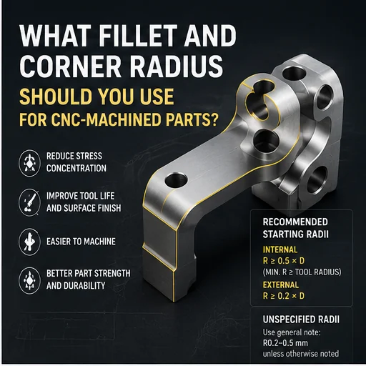
Fillets and corner radii have a direct effect on whether a CNC-machined part can be produced with a rigid, efficient cutting tool or requires small cutters, long cycle times, additional setups, electrical discharge machining, or manual finishing. They also influence stress concentration, fatigue life, coating coverage, assembly clearance, and the final appearance of the component.
The correct radius is not one universal value. An internal pocket corner is controlled by end-mill diameter and toolpath behavior. A bottom fillet between a wall and floor is controlled by the cutter’s corner geometry. An external edge radius may be selected for handling safety or stress reduction. A shaft shoulder fillet may be limited by the chamfer of a bearing, washer, seal, or mating hub.
For CNC milling, the most important design rule is that an internal corner should not be designed at exactly the same radius as the cutting tool. When the cutter fits the corner with no clearance, tool engagement rises sharply, feed must drop, vibration becomes more likely, and the surface can show chatter or overcut. A larger part radius allows the tool to flow through the corner with a smoother path.
This guide explains how to select internal and external fillets for milled and turned parts, how radius relates to cutter diameter and pocket depth, when sharp corners are unavoidable, how to use relief features, how radii affect stress and assembly, and how to specify and inspect them correctly.
What Is the Difference Between a Fillet, Radius, and Chamfer?
The terms fillet and radius are often used interchangeably, but the location and function of the rounded feature should be clear before it is dimensioned.
Internal Fillets
An internal fillet is a concave rounded transition between two surfaces. Common examples include:
- The vertical corners of a milled pocket
- The transition between a pocket wall and floor
- The root of a rib or boss
- The shoulder between two turned diameters
- The intersection of two internal walls
Internal fillets are limited by cutter geometry. A rotating end mill naturally leaves a radius in a vertical inside corner. A bull-nose or corner-radius cutter leaves a radius where a wall meets a floor.
External Corner Radii
An external radius is a convex rounded edge on the outside of a part. It may be used to:
- Remove a sharp handling edge
- Reduce stress concentration
- Improve coating coverage
- Match an adjacent housing or industrial design
- Reduce the risk of edge chipping
External radii are generally less restrictive than internal radii because the cutter can approach from outside the material. They may still require a form tool, corner-rounding cutter, ball end mill, or additional contouring pass.
Chamfers
A chamfer is a flat angled surface rather than a curved transition. Chamfers are often used for:
- General edge breaking
- Fastener entry
- Deburring
- Weld preparation
- Assembly guidance
- Providing clearance for a mating radius
A chamfer is usually faster and easier to inspect than a cosmetic external radius. A radius is often preferable where stress flow, sealing, repeated handling, or appearance requires a smooth curve.
| Feature | Geometry | Typical purpose | Common CNC method |
|---|---|---|---|
| Vertical internal corner | Concave radius in plan view | Required by rotating end-mill geometry | Flat end mill or end mill with suitable diameter |
| Wall-to-floor fillet | Concave radius in section view | Stress relief, clean transition, or tool geometry | Bull-nose, corner-radius, or ball end mill |
| External edge radius | Convex curve | Handling, appearance, coating, or stress control | Corner-rounding tool, ball end mill, or contour milling |
| Chamfer | Flat angled face | Deburring, lead-in, and mating clearance | Chamfer mill, spot drill, or turning tool |
| Turned shoulder radius | Concave rotational fillet | Reduce stress at diameter change | Turning insert nose radius or formed toolpath |
| Corner relief | Localized pocket beyond nominal corner | Allow square mating part to fit | Dog-bone, T-bone, drilled relief, or EDM |
Why Can’t a Standard End Mill Produce a Sharp Internal Corner?
A standard end mill rotates around a circular axis. Its outside cutting envelope is circular, so it cannot enter an internal 90-degree corner and remove the final material point at the theoretical intersection of two flat walls.
The Tool Radius Becomes the Minimum Geometric Radius
A 10 mm diameter flat end mill has a nominal radius of 5 mm. If it machines a pocket corner, the smallest theoretical corner it can leave is approximately R5, before considering runout, tool deflection, finish allowance, and toolpath control.
A smaller cutter can create a smaller internal radius, but it normally has:
- Lower stiffness
- Lower material-removal capacity
- Greater deflection risk
- Lower allowable feed
- Higher breakage risk in deep pockets
Reducing the corner radius can therefore increase both roughing and finishing time.
A Corner Equal to the Tool Radius Is Poor for Toolpath Flow
Even if a 10 mm cutter can theoretically create an R5 corner, designing the finished corner as exactly R5 forces the tool center into a zero-clearance path. Radial engagement rises sharply as the cutter enters the corner.
Autodesk’s Fusion guidance warns that forcing a tool into a sharp corner, or into a corner whose radius equals the tool radius, can cause chatter and distort surface finish. Sandvik Coromant similarly recommends machining a larger component corner radius rather than using the traditional condition where the corner equals half of cutter diameter.
Sharp Corners Need a Different Manufacturing Method
A genuinely sharp internal corner may require:
- Wire EDM for through features
- Sinker EDM for blind cavities
- Broaching
- Slotting or shaping
- Manual filing for low-risk prototypes
- A relief pocket that allows a square mating part to fit
These methods may be justified when the corner is functionally necessary, but they should not be added only because the CAD model was created with ideal square geometry.
What Internal Corner Radius Should You Start With?
The best starting radius is one that allows a practical cutter to enter the feature while retaining clearance between the cutter radius and part radius.
Make the Part Radius Larger Than the Cutter Radius
A useful starting rule is:
Do not specify the internal part radius equal to the intended end-mill radius. Leave enough additional radius for the cutter to turn through the corner.
Autodesk has recommended using a tool radius around 80% of the minimum concave part radius as a rule of thumb. This means a finished R5 internal corner would preferably be machined with a tool radius of about R4 or smaller, such as an 8 mm diameter cutter rather than a 10 mm cutter.
This is a practical starting point rather than a universal standard. Hard material, deep walls, long tools, strict finish requirements, and heavy roughing may benefit from even more clearance.
Use a Larger Radius When It Does Not Affect Assembly
Increasing an internal radius can allow:
- A larger and stiffer end mill
- Higher feed and material-removal rate
- Smoother tool motion
- Lower vibration
- Longer tool life
- More uniform surface finish
If a pocket only holds a cable, electronic module, weight-reduction space, or nonmating component, a large radius may have no functional disadvantage.
Standardize Radius Values Across the Part
Using several nearly identical internal radii can force additional tools and programming operations. Where function allows, use a small family of standard radii, such as one common vertical-corner radius and one common bottom fillet.
Standardization can reduce:
- Tool changes
- Finish passes
- Programming complexity
- Inspection features
- Risk of using the wrong cutter
| Finished internal radius | Example practical cutter | Comment |
|---|---|---|
| R2 mm | Approximately 3 mm diameter or smaller | Small cutter; review depth and material carefully |
| R3 mm | Approximately 4–5 mm diameter | More practical than using a 6 mm cutter at zero clearance |
| R5 mm | Approximately 8 mm diameter or smaller | Allows clearance compared with a 10 mm cutter |
| R8 mm | Approximately 12 mm diameter or smaller | Supports a stiffer tool for moderate-depth pockets |
| R12 mm | Approximately 16–20 mm diameter | Useful for larger cavities and high removal rates |
| Sharp corner | Not possible with a standard rotating end mill alone | Use relief, EDM, broaching, or redesign |
The examples above are DFM starting points, not mandatory tool assignments. The actual cutter depends on access, pocket width, material, spindle capability, flute length, holder clearance, and finishing strategy.
How Should Pocket Depth Affect the Corner Radius?
A radius that is easy to machine in a shallow pocket may be difficult at the bottom of a deep cavity. Depth controls cutter length, overhang, stiffness, chip evacuation, and holder clearance.
Deep Pockets Need Larger Cutters
A long, small-diameter end mill behaves like a slender beam. As tool overhang increases, the cutter becomes more sensitive to:
- Deflection
- Chatter
- Runout
- Tool breakage
- Tapered walls
- Poor corner finish
A larger corner radius permits a larger-diameter cutter and can significantly improve stability.
Use Radius-to-Depth Rules as Screening Tools
Autodesk University DFM guidance has suggested that an internal fillet radius greater than one-third of the vertical wall height is a useful general starting point. For a 30 mm deep pocket, this would suggest considering an internal radius greater than approximately 10 mm.
This is not a universal requirement. Modern long-reach tooling can machine smaller radii, and part function may require them. The rule is useful for identifying features likely to increase cost and risk.
Separate Roughing Radius from Final Corner Radius
A common process is to rough the cavity with a large cutter, leave material in the corners, and finish the final radius using a smaller tool.
This approach is more efficient than machining the complete pocket with the smallest cutter, but the final corner still adds:
- An extra tool
- Rest-machining toolpaths
- Longer cycle time
- Possible witness marks between tools
If the corner can be enlarged enough for the roughing cutter to finish it directly, the operation becomes simpler.
How Should You Design Bottom Fillets Between Walls and Floors?
The radius at the bottom of a pocket is different from the radius in the vertical plan-view corner. These two radii may require different tools and should not automatically be assigned the same value.
A Flat End Mill Naturally Produces a Small or Sharp Bottom Corner
A nominal flat end mill can create a nearly flat floor and a nominally sharp wall-to-floor intersection, but the tool itself often has a small edge preparation or corner radius for strength. A perfectly sharp machined intersection is therefore difficult to guarantee.
If the design simply needs a normal milled pocket, avoid applying a tight controlled zero-radius requirement to the bottom corner.
Use a Bull-Nose Cutter for a Controlled Bottom Fillet
A bull-nose or corner-radius end mill has a flat central area and rounded cutting edges. Autodesk notes that the rounded corner is less prone to breakage than the sharp corner of a flat end mill, which is one reason these tools are used in roughing and profile operations.
A controlled bottom radius can:
- Reduce stress concentration
- Strengthen the cutting edge
- Improve tool life
- Create a smooth wall-to-floor transition
Large Bottom Fillets May Need 3D Contouring
If the bottom fillet is large relative to the cutter, the part may require a ball end mill or 3D contour path. This can create:
- Longer finishing time
- Scallop-height considerations
- Additional surface-finish inspection
- Limited access near adjacent walls
Use a large sculpted fillet only when stress, flow, cleaning, or appearance requires it.
Should All Internal Fillets Have the Same Radius?
Using the same radius everywhere may simplify CAD, but it does not always simplify machining. Vertical corners, bottom transitions, rib roots, and turned shoulders have different tool constraints.
Use One Radius for Similar Vertical Corners
Standardizing vertical corner radii in the same pocket or feature family can allow one cutter to complete multiple areas.
Avoid sequences such as R5, R5.5, R6, and R6.5 unless each value is functionally required.
Use a Different Bottom Radius When Appropriate
A pocket may have an R6 vertical corner and an R1 bottom fillet. This can be practical because:
- An 8 or 10 mm end mill can machine the vertical corners
- A standard corner-radius tool can create the bottom transition
- The floor remains mostly flat
Requiring R6 in both directions may force a ball-end or form-tool operation.
Separate Structural Radii from Cosmetic Edge Radii
A structural fillet at a rib root may be much larger than the small external radius used to break handling edges. These features should have separate design criteria and callouts.
When Should You Use an External Radius Instead of a Chamfer?
Both features remove sharp external edges, but they create different stress, appearance, inspection, and manufacturing conditions.
Use Chamfers for Simple Edge Breaking and Assembly
Chamfers are usually preferred for:
- Fastener and pin lead-ins
- General burr removal
- Edges hidden after assembly
- Electrical connector guidance
- Clearance around mating shoulder radii
A chamfer can often be machined rapidly with a standard chamfer mill or turning tool.
Use External Radii for Repeated Handling or Stress Flow
An external radius may be preferable when:
- Operators repeatedly touch the edge
- The part has a visible industrial-design requirement
- Paint, plating, or coating must wrap around the edge
- A curved load path is beneficial
- The edge must avoid cutting seals, cables, or soft components
Do Not Over-Specify Cosmetic Radii
A general note such as “break all sharp edges 0.2–0.5 mm” may be more economical than individually dimensioning every external edge.
Use individually controlled radii only where the finished curve affects:
- Mating geometry
- Minimum wall thickness
- Product appearance
- Safety
- Stress performance
How Do Fillets Reduce Stress Concentration?
A sharp change in cross-section creates a local stress concentration. A smooth radius can distribute load over a wider region and reduce peak stress.
Larger Radii Usually Improve Stress Distribution
Increasing a fillet radius generally reduces the severity of a geometric discontinuity. This is important around:
- Shaft shoulders
- Rib roots
- Boss transitions
- Loaded pocket corners
- Mounting lugs
- Cyclically loaded brackets
The amount of improvement depends on geometry, load direction, material, surface condition, and residual stress.
A Radius Does Not Replace Structural Analysis
A convenient machining radius is not automatically adequate for fatigue, pressure, or aerospace loading. Critical parts may require:
- Finite-element analysis
- Stress-concentration-factor data
- Fatigue calculations
- Physical testing
- Industry-specific design rules
Manufacturability should be optimized within the structural requirement, not substituted for it.
Surface Finish at the Fillet Also Matters
Tool marks, chatter, grinding scratches, or EDM recast at a highly stressed fillet can act as local crack-initiation sites. A structural radius may therefore need a surface-finish requirement and controlled toolpath direction.
How Should You Design Shaft and Bearing Shoulder Fillets?
Turned shoulder fillets are often governed by the mating component rather than by machining convenience alone.
Check the Mating Component’s Chamfer or Corner Clearance
A bearing ring, washer, gear, seal, or hub may have a specified chamfer. The shaft or housing fillet must fit inside the available clearance so the mating face can seat fully.
If the shaft fillet is too large:
- The bearing may contact the radius instead of the shoulder
- The part may not seat axially
- Preload or alignment can be incorrect
- Stress may be transferred through an unintended edge
Use the Largest Radius That Still Clears the Mating Part
The preferred design normally balances:
- Stress reduction
- Bearing or component chamfer clearance
- Turning insert nose radius
- Grinding-wheel access
- Inspection method
ISO 582:2026 specifies chamfer boundaries for metric rolling bearings and provides recommendations for corresponding housing and shaft fillet radii. Designers working with bearings should use the actual bearing manufacturer’s boundary dimensions and the applicable standard.
Use Relief Grooves When a Large Fillet Cannot Fit
An undercut or relief groove can allow the mating component to seat against a flat shoulder while preserving machining access. Reliefs are common on:
- Ground shaft shoulders
- Thread runouts
- Bearing seats
- Seal lands
A groove introduces its own stress concentration and should be selected from an appropriate standard or verified by analysis.
How Do Thin Walls and Ribs Change Fillet Selection?
Adding a radius consumes local space. On thin walls or closely spaced features, a large fillet can reduce the flat seating area or create uneven wall thickness.
Do Not Let the Fillet Consume the Functional Floor
In a narrow pocket, two large bottom fillets may meet and eliminate the flat floor. This can affect:
- Component seating
- Seal placement
- Adhesive thickness
- Inspection access
- Drainage
Model the actual tangent geometry rather than adding fillets late in the design.
Use Smooth Rib Transitions
A rib meeting a wall or base with a sharp root can create high local stress. A root fillet can improve load transfer, but it should not become so large that it blocks a mating component or creates an inaccessible undercut.
Consider Tool Access Between Adjacent Walls
The cutter diameter selected by the corner radius must also fit through the pocket opening and between nearby bosses. A large radius does not help if the tool holder cannot reach the feature.
What If a Square Component Must Fit into a Milled Pocket?
A rectangular electronic module, key, plate, insert, or other square-cornered component cannot sit fully into a standard milled pocket with rounded corners unless clearance is added.
Enlarge the Pocket Corner Radius and Reduce the Mating Part Corner
The simplest solution is often to add a chamfer or external radius to the mating component. This allows it to fit inside a normally milled pocket.
Use Dog-Bone or T-Bone Reliefs
A dog-bone relief extends a circular cut beyond the nominal pocket corner so the square mating corner has clearance. A T-bone relief places the cutter center along one wall rather than the corner bisector.
These features are common in routed sheet products and may also be used in milled parts when:
- The mating component must remain square
- The relief is not in a sealing area
- Local material removal is structurally acceptable
- The appearance is acceptable
Use EDM Only When the Sharp Corner Is Truly Required
Wire or sinker EDM may be justified for mold inserts, dies, keyways, precision nests, and hardened components. It adds process time, cost, and inspection requirements, so it should not be the default for a general equipment pocket.
How Do Corner Radii Affect Surface Finish and Tool Life?
Corner geometry changes cutter engagement. The resulting load variation affects vibration, heat, deflection, and visible tool marks.
Tight Corners Create Engagement Spikes
As an end mill enters a tight internal corner, more of its circumference contacts the material. The effective chip load and cutting force can rise unless the CAM system reduces feed or uses a constant-engagement strategy.
Sandvik states that good machine dynamic stability and tool-center feed reduction control are important for successful internal-corner milling.
Corner Smoothing Improves Toolpath Motion
CAM systems can add a minimum cutting radius or smoothing arc to prevent an abrupt directional change. This can improve:
- Feed consistency
- Surface finish
- Machine motion
- Tool life
- Cycle predictability
The finished part geometry must allow this smoothing. A mathematically sharp or zero-clearance corner removes that option.
Corner-Radius Cutters Have Stronger Cutting Edges
A tool with a small corner radius is stronger than a perfectly sharp-edged flat end mill. The radius distributes cutting load and reduces local edge chipping.
The selected cutter radius must still match the floor fillet and leave the required flat surface.
How Do Materials Affect Practical Corner Radius?
The same radius and depth can be straightforward in aluminum but difficult in hardened steel, titanium, or a nickel alloy.
Aluminum Allows More Aggressive Small-Tool Cutting
Aluminum’s machinability often permits smaller cutters, higher feeds, and deeper flutes than harder materials. However, long small tools can still chatter or accumulate adhesive chips.
Cosmetic aluminum parts also need consistent toolpath blending because anodizing can reveal corner chatter or finish variation.
Stainless Steel and Titanium Benefit from Larger Radii
Stainless steel, titanium, and nickel alloys can generate higher force and heat. Small cutters in deep corners are more vulnerable to:
- Deflection
- Work hardening
- Built-up edge
- Chipping
- Rapid wear
A larger corner radius allows a stiffer tool and more stable engagement.
Hardened Materials May Need Grinding or EDM
After heat treatment, small internal radii may require hard milling, grinding, or EDM. The design should coordinate rough-machining allowance, heat-treatment distortion, and final corner process.
How Do Surface Treatments Affect Radii and Edges?
A finish may build on, remove, or react differently at a corner. Radii should be evaluated in the finished condition.
Coatings Build Around Internal and External Radii
Processes such as plating, PVD, paint, powder coating, and hard anodizing affect edge and corner geometry differently.
Possible issues include:
- Reduced clearance in internal corners
- Thicker paint or powder accumulation
- Thin coverage on sharp external edges
- Hard-anodized edge chipping
- Masking boundaries near radii
Sharp Edges Are Difficult to Coat Reliably
Many coatings pull away from, thin at, or become stressed around sharp edges. A controlled radius can improve coverage and reduce handling damage.
Finishing May Change the Measured Radius
Electropolishing, abrasive blasting, polishing, and deburring can remove or round edge material. Critical radii should be measured after all relevant finishing processes.
How Should Fillets and Radii Be Toleranced?
A radius should not receive a tight tolerance merely because CAD software displays many decimal places. The tolerance should reflect mating, stress, appearance, and inspection needs.
Use General Tolerances for Noncritical Radii
ISO 2768-1 covers general tolerances for linear dimensions including radii, external radii, and chamfer heights when individual tolerances are not stated.
A drawing may apply an appropriate general tolerance for ordinary edge and pocket radii while individually controlling only functional features.
Use Profile Tolerance for Complex Blended Surfaces
A sculpted transition involving multiple tangent curves may be better controlled with profile of a surface rather than separate radius dimensions.
ASME Y14.5-2018, reaffirmed in 2024, establishes rules for geometric dimensioning and tolerancing, including profile controls and related datum references.
Define Surface Texture Where the Radius Is Highly Stressed
ASME Y14.36-2018, reaffirmed in 2024, provides drawing methods for surface-texture symbols. ASME B46.1-2019, reaffirmed in 2026, addresses surface roughness, waviness, and lay.
Specify roughness on a fillet only when it affects fatigue, sealing, flow, friction, or appearance.
How Should Radii Be Shown on a CNC Drawing?
The drawing or model-based definition should identify the radius, its location, quantity, and whether it is typical or applies to all similar features.
Use Clear Radius Callouts
A radius callout may include:
- R value
- Tolerance
- Quantity
- Reference to similar features
- Surface-finish requirement
- Finished-condition requirement
Avoid notes such as “add generous fillets” because they do not define inspectable geometry.
Do Not Let the Drawing Conflict with the CAD Model
Common conflicts include:
- The model has R5 while the drawing states R6
- The model contains a variable-radius blend but the drawing calls out one constant value
- The drawing says sharp while the model contains a radius
- A general edge-break note overlaps a controlled mating radius
The controlling product definition must be clear.
State Whether the Radius Applies Before or After Finishing
For plated, anodized, polished, or electropolished parts, specify whether the final radius is evaluated on the finished surface.
Example internal-corner note: Internal vertical pocket corners R6 ± 0.3 unless otherwise specified. Final corner profile shall be free of chatter and steps exceeding the specified surface requirement. Bottom wall-to-floor fillet R1.0 maximum.
Example edge note: Break unspecified external sharp edges 0.2–0.5 mm by chamfer or radius. Do not break identified sealing, datum, or cutting edges.
How Are Fillets and Corner Radii Inspected?
The inspection method depends on radius size, access, tolerance, and whether the feature is a simple arc or a complex blended surface.
Radius Gauges and Optical Comparators
Radius gauges are useful for workshop checks of accessible concave and convex radii. Optical comparators can inspect small profiles, turned shoulders, cutter forms, and external edges.
These methods may be insufficient for deep pocket corners or freeform blends.
CMM and Profile Scanning
A coordinate measuring machine can sample points or scan a radius relative to datums. Optical scanners and contour-measuring systems may also evaluate accessible profiles.
Inspection planning should define:
- Probe size
- Sampling density
- Evaluation method
- Datum alignment
- Whether adjacent tangent surfaces are included
Use Functional Inspection for Mating Clearance
When the purpose of a radius is to clear a bearing chamfer or fit a square component, a functional gauge or mating-part check may provide more meaningful acceptance than an isolated radius measurement.
| Radius feature | Typical inspection method | Main limitation |
|---|---|---|
| Large accessible external radius | Radius gauge, template, CMM, or optical scan | Gauge contact may not reveal profile error |
| Small internal pocket corner | CMM, optical method, or replica | Probe access and corner depth |
| Turned shoulder fillet | Optical comparator or contour tracer | Part alignment and tangent interpretation |
| Complex blended fillet | CMM scanning or 3D optical comparison | Requires defined profile tolerance and datums |
| Bearing-clearance radius | Functional gauge or mating component | May not quantify exact radius |
| General broken edge | Visual and tactile inspection | Not suitable for a tightly controlled radius |
What Fillet and Radius Choices Increase CNC Cost?
Cost rises when a radius forces a small tool, special tool, extra setup, rest machining, 3D finishing, or nonmilling process.
Very Small Internal Radii
A small radius can require:
- Small-diameter end mills
- Long-reach tools
- Slow finishing passes
- Frequent tool replacement
- Additional corner cleanup
Many Different Radius Values
Each unique bottom radius may require a different bull-nose or form tool. Each vertical radius can require another end-mill diameter or toolpath.
Sharp Internal Corners and Undercuts
Sharp corners, reverse fillets, and inaccessible blends may require EDM, broaching, lollipop cutters, custom form tools, or multiple setups.
Use these features only when their function justifies the manufacturing route.
How Can You Select a Radius Step by Step?
A practical selection process prevents the radius from being chosen only by appearance.
Step 1: Identify the Functional Limit
Determine the maximum and minimum radius allowed by:
- Mating parts
- Stress analysis
- Seal or bearing clearances
- Available flat seating area
- Appearance
Step 2: Identify a Practical Cutter
Review:
- Pocket width
- Depth
- Material
- Tool access
- Holder clearance
- Required surface finish
Select a cutter that is stiff enough for the feature, then make the part radius larger than the cutter radius.
Step 3: Validate the Complete Process
Check whether the part also requires:
- Heat treatment
- Grinding
- Anodizing or coating
- Special inspection
- Functional assembly testing
For high-risk parts, validate the radius through prototype machining or first-article inspection.
How Does RapidMFGPro Support Fillet and Radius Design Reviews?
Fillet manufacturability depends on pocket depth, tool access, material, setup direction, stress requirement, surface finish, downstream treatment, and inspection. RapidMFGPro operates as a manufacturing resource and supplier-matching platform and helps connect projects with resources suited to the complete requirement.
Reviewing CAD Geometry Before Supplier Matching
A design review can identify:
- Internal radii equal to cutter radius
- Deep pockets with very small corners
- Unnecessary sharp corners
- Conflicting vertical and bottom radii
- Square components that cannot fit the pocket
- Bearing shoulders with excessive fillets
- Radii that disappear after coating or polishing
Matching the Required CNC Capability
The manufacturing route may require:
- Three-axis or five-axis milling
- Long-reach or damped tooling
- Turning and grinding
- Ball-end or corner-radius finishing
- Wire or sinker EDM
- Profile inspection
Validating Critical Corners Before Production
Prototype or first-article parts can confirm:
- Actual corner radius
- Chatter and surface finish
- Mating-component clearance
- Edge condition after finishing
- Stress-test or fatigue performance when required
The approved cutter, toolpath, finish, and inspection method can then be retained for repeat production.
Frequently Asked Questions About CNC Fillets and Corner Radii
What Is the Minimum Internal Radius for CNC Milling?
The theoretical minimum is approximately the radius of the selected end mill, but designing the part at exactly that value creates poor corner engagement. Use a part radius larger than the cutter radius and consider depth, material, and tool stiffness.
Can a CNC Mill Make a Perfectly Sharp Internal Corner?
Not with a standard rotating end mill alone. Sharp internal corners require relief features, EDM, broaching, slotting, or another special process.
Is a Larger Fillet Always Better?
No. A larger fillet usually helps stress and machining, but it can interfere with mating parts, remove seating area, block tool access, or consume thin walls.
Should the Bottom Fillet Match the Vertical Corner Radius?
Not necessarily. A pocket can use a larger vertical corner radius for end-mill access and a smaller wall-to-floor radius created by a corner-radius cutter.
Is a Chamfer Cheaper Than a Radius?
For simple external edge breaking, a chamfer is usually faster and easier to inspect. A radius may be justified for handling, stress, coating, sealing, or appearance.
How Do I Fit a Square Part into a Rounded CNC Pocket?
Chamfer or radius the mating part, add dog-bone or T-bone corner reliefs, or use EDM when the pocket must remain sharp.
Do Corner Radii Change After Anodizing or Plating?
Yes. Additive coatings build on surfaces, while polishing and electropolishing remove material. Critical radii and clearances should be evaluated in the finished condition.
How Tight Should a Radius Tolerance Be?
Use a general tolerance for noncritical radii. Apply a tighter individual tolerance only when the radius controls fit, stress, sealing, bearing clearance, appearance, or another verified function.
Conclusion
For CNC-milled parts, choose an internal corner radius larger than the intended cutter radius rather than matching it exactly. Increase the radius as pocket depth and material difficulty increase, and use separate values for vertical corners and wall-to-floor fillets when that simplifies tooling.
External radii should be reserved for stress, safety, coating, or appearance requirements; ordinary edge breaking is often more economical with a chamfer. Bearing shoulders, seals, and mating parts must define the maximum allowable fillet.
RapidMFGPro helps review these relationships and match CNC projects with suitable milling, turning, EDM, finishing, and inspection resources.
Reference Sources
- Sandvik Coromant — Milling Inside Corners
- Sandvik Coromant — Milling Holes, Cavities, and Pockets
- Sandvik Coromant — Slicing and Trochoidal Milling
- Autodesk Fusion — How to Machine Internal Corners Correctly
- Autodesk Fusion Help — Pocket Clearing and Minimum Cutting Radius
- Autodesk University — Designing for Manufacture
- Autodesk Fusion — Milling Tool Types and Corner-Radius End Mills
- ISO 22037:2007 — Solid End Mills with Corner Radii
- ISO 582:2026 — Rolling Bearing Chamfer Dimensions and Fillet Recommendations
- ISO 2768-1:1989 — General Tolerances for Linear and Angular Dimensions
- ASME Y14.5-2018 (R2024) — Dimensioning and Tolerancing
- ASME Y14.36-2018 (R2024) — Surface Texture Symbols
- ASME B46.1-2019 (R2026) — Surface Texture
Need Help Reviewing a Custom Part?
Share your CAD file and requirements to request supplier matching. Supplier capability and commercial terms must be verified before order placement.
Request Supplier Match