Time to read: 22 min
What Is CNC Drilling? How Precision Holes Are Machined
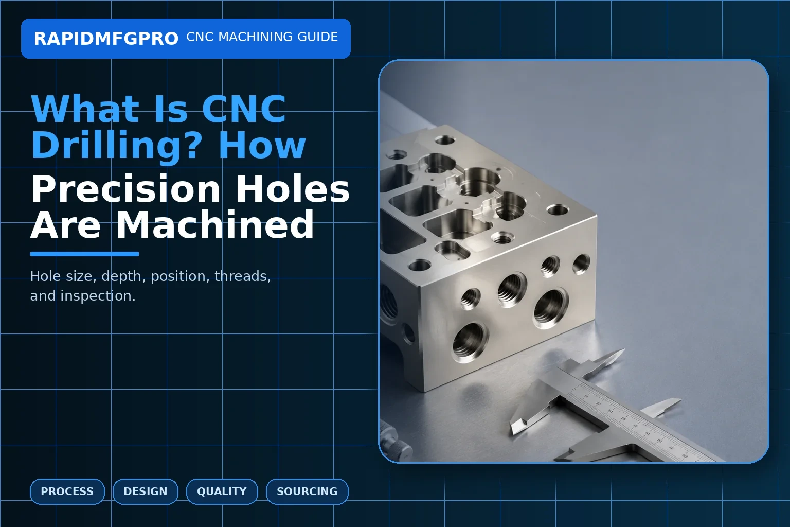
Direct answer: Drilling is a machining process that uses a rotating drill to create a hole. Precision hole production often includes more than drilling: spotting starts the location, drilling removes most material, boring or reaming controls diameter and form, tapping or thread milling creates threads, and countersinking or counterboring creates fastener seats. To machine a reliable hole, the drawing must define diameter, depth, position, tolerance, thread, surface finish, datum references, and whether the hole is through or blind.
Holes are among the most common features in custom parts, but they are also a frequent source of assembly problems. A hole can be the correct diameter yet fail because it is misplaced, angled, burred, too shallow, rough, or distorted by coating. Deep holes add chip-removal and straightness risks. This guide explains how precision holes are machined and how RapidMfgPro can help identify independent suppliers with the appropriate drilling, boring, reaming, threading, and inspection capability.
What Is Drilling in CNC Machining?
A drill creates a cylindrical hole by axial cutting
During drilling, a rotating drill advances into the workpiece along its axis. Cutting edges at the drill point remove material, while flutes carry chips out of the hole. In a machining center, the tool usually rotates and the workpiece remains clamped. In a turning center, a drill may remain on center while the workpiece rotates, or a live tool may drill off-axis features.
Standard twist drills are widely used, but they are not the only option. Indexable drills remove material quickly in larger diameters. Solid-carbide drills offer stiffness and accuracy. Spade drills and gun drills support specific diameter or depth ranges. Center drills and spotting drills create an accurate starting location.
A drilled hole is not automatically a precision bore. The final diameter, roundness, straightness, finish, and position depend on tool design, material, depth, machine rigidity, coolant, and subsequent operations.
Hole-making is a sequence of operations
A common sequence is spot drill, drill undersize, then ream to final diameter. Another sequence is drill, rough bore, and finish bore. A threaded hole may be drilled to the correct tap size, chamfered, tapped, and gauged. A flat-bottom blind hole may require an end mill or special drill after the initial hole.
The correct sequence is chosen from function. A clearance hole for a cover screw may need only drilling and deburring. A dowel hole locating two assemblies may need drilling and reaming in one setup. A bearing bore may need boring, honing, or grinding.
| Operation | Main purpose | Typical capability | When it is used |
|---|---|---|---|
| Spot drilling | Start the hole accurately | Controls drill entry location | Before drilling on flat or angled surfaces |
| Drilling | Remove most hole material | General diameter and depth | Clearance holes, pilot holes, rough holes |
| Boring | Correct size, location, and alignment | Improved diameter and geometry | Precision bores and related hole axes |
| Reaming | Finish a predrilled hole | Good size and surface finish | Dowel, pin, and close-fit holes |
| Honing | Improve bore form and finish | Fine surface and cylindrical control | Hydraulic, engine, and precision sliding bores |
| Tapping/thread milling | Create an internal thread | Specified thread size and class | Fastener and adjustment interfaces |
Which Hole Types Must Be Defined on the Drawing?
Through holes and blind holes have different risks
A through hole exits the opposite side of the part. It generally allows easier chip evacuation and full tool breakthrough. However, breakthrough can create a burr or damage a nearby surface. A blind hole stops at a defined depth. It needs room for the drill point, chips, and any thread runout.
Drawing depth must be unambiguous. For a blind drilled hole, “depth” may refer to full-diameter depth or total drill-point depth. Threads also need effective thread depth rather than only drilled depth. A supplier should not have to guess whether a bottom angle is acceptable.
Intersecting holes require special attention because chips and burrs can remain at the intersection. Fluid manifolds, valve blocks, and medical pump components often need defined cleaning and borescope inspection.
Counterbores, countersinks, and spotfaces serve different functions
A counterbore creates a cylindrical recess with a flat bottom, usually for a socket-head screw or bolt head. A countersink creates a conical seat for a flat-head fastener. A spotface creates a shallow flat bearing surface on an otherwise uneven or cast surface.
The drawing should state diameter, depth or included angle, and relation to the main hole. If a countersink must control flushness, identify the fastener standard or resulting head condition. Over-countersinking can weaken thin material and leave the screw below the surface.
How Are Precision Hole Size and Position Achieved?
Tool choice controls diameter and form
Drills can wander, especially when entering an angled surface, crossing a cavity, or drilling deep. A spot drill provides a controlled start. Pilot holes may guide large drills, but poorly selected pilot sizes can destabilize an indexable drill. The supplier should follow the tool manufacturer’s intended method.
Reaming improves a predrilled hole, but it removes only a small amount of stock and follows the existing path. It cannot reliably correct a badly misplaced or crooked hole. Boring uses a single-point tool and can correct location and alignment more effectively. Interpolation with an end mill can create bores, but its roundness and finish depend on machine condition and toolpath.
Datum strategy controls position
A hole is often functional because of where it is, not only its diameter. Dowel holes, bolt patterns, bearing bores, and optical apertures must be located relative to datums that represent the assembly. Position tolerance communicates this relationship better than isolated ± coordinate tolerances.
Related holes should be machined in one setup when practical. If the part is repositioned, fixture and datum transfer errors accumulate. Probing can help locate the workpiece, but it cannot eliminate movement or deformation after unclamping.
| Hole requirement | Recommended process | Key control | Inspection |
|---|---|---|---|
| General clearance hole | Spot and drill | Diameter, breakthrough, burr removal | Pin or caliper as appropriate |
| Dowel hole | Drill undersize and ream | One-setup position and finish allowance | Gauge pin and CMM/functional fixture |
| Precision bearing bore | Drill, bore, then hone or finish if required | Datum axis, roundness, thermal stability | Bore gauge, air gauge, CMM |
| Threaded blind hole | Drill, chamfer, tap or thread mill | Effective thread depth and chip control | GO/NO-GO thread gauge |
| Deep small-diameter hole | Special deep-hole drill or gun drill | Coolant delivery, straightness, chip evacuation | Depth, flow, borescope, CT if justified |
| Angled hole | Spotface/spot drill then drill in rigid setup | Entry surface and angular datum | CMM or dedicated gauge |
What Makes Deep-Hole Drilling Difficult?
Chip evacuation becomes the main process risk
As hole depth increases, chips travel farther through the flutes. Packed chips increase torque, scratch the bore, push the drill off line, or break the tool. Peck drilling periodically retracts the tool to clear chips, but excessive pecking can increase cycle time and leave marks.
Through-tool coolant helps carry chips out and cool the cutting edge. Gun drilling uses a specialized tool, guide support, and high-pressure coolant to create deep straight holes. The appropriate method depends on diameter-to-depth ratio, material, straightness, finish, and quantity.
Blind deep holes need a plan for the remaining chip and coolant. A hole that cannot be cleaned or inspected may not be acceptable in fluid, vacuum, medical, or high-reliability applications.
Drill wander affects exit location and wall thickness
A drill can bend or follow material variations. The exit point may differ from the entry position. If the hole passes near an outer wall or intersects another passage, wander can create a thin wall or miss the target.
Designers should avoid unnecessarily extreme depth-to-diameter ratios and provide enough surrounding material. When a deep channel can be made by drilling from two ends, the meeting point may create a step. This should be evaluated for flow and cleaning.
How Are Threads Machined in Holes?
Tapping is efficient for standard threads
A tap cuts or forms the complete thread profile as it enters the hole. Cutting taps create chips. Form taps displace material and are used only in suitable ductile materials with the correct pilot diameter. Spiral-point taps push chips forward in through holes, while spiral-flute taps pull chips out of blind holes.
The tap drill size, thread engagement, lubricant, and alignment affect strength and tool life. Excessive thread engagement increases torque without providing proportional strength. A blind hole needs enough extra drill depth for the tap chamfer and chip space.
Thread milling offers flexibility and risk control
A thread mill follows a helical path and can create threads larger than the tool. It can produce right-hand or left-hand threads, adjust size by offset, and machine near the bottom of a blind hole. If the tool breaks, removal may be easier than removing a broken tap.
Thread milling is useful for large threads, hard materials, expensive parts, or applications needing size adjustment. It is slower than tapping for some small standard holes. The supplier should choose the method based on quantity, material, thread size, depth, and risk.
| Thread detail | What the drawing should state | Why it matters | Common error |
|---|---|---|---|
| Thread designation | Metric/Unified/Pipe standard, pitch or TPI, class | Defines profile and fit | Ambiguous “M6” or “1/4 thread” note |
| Effective depth | Minimum full thread engagement | Separates useful thread from drill depth | Tap cannot reach required full profile |
| Blind bottom | Allowed drill point and runout | Controls remaining material | Thread specified to an impossible flat bottom |
| Coating | Masking or size allowance | Coating can tighten the fit | Fastener binds after anodizing or plating |
| Inspection | Gauge class or mating-part test | Defines acceptance | Pitch diameter not properly verified |
How Should Holes Be Designed for Manufacturability?
Use standard sizes and provide access
Standard drill, reamer, counterbore, and thread sizes reduce special tooling. Keep enough distance between holes, edges, pockets, and walls. A hole close to a free edge can break out or distort. A counterbore in a thin wall may leave insufficient material.
A drill should enter a reasonably flat surface. On a curved or angled face, add a spotface where possible or allow a suitable 5-axis approach. Intersecting angled holes can produce thin edges and hidden burrs.
Do not specify a sharp internal bottom unless it is functional. Standard drills leave a conical point. Flat-bottom tools exist but add cost and may need a pilot operation.
Separate functional holes from noncritical holes
Dowel holes, bearing bores, injector ports, and optical apertures may need tight position and finish. Simple cover holes may use general tolerances. Applying the same tolerance to every hole increases cost and inspection time.
Use basic dimensions and position tolerance for patterns where appropriate. Identify datum targets if the part is irregular. For castings or weldments, specify whether hole location references the raw shape or machined datums.
How Are Drilled Holes Inspected?
Size, depth, and thread need the correct gauges
Small diameters may be checked with calibrated pin gauges. Larger bores may use bore gauges, air gauges, inside micrometers, or CMM measurement. A depth micrometer or calibrated depth gauge checks blind depth. Threads use GO/NO-GO plug gauges or more detailed pitch-diameter methods.
No single tool verifies every characteristic. A pin gauge may confirm size but not position. A CMM may report position but may not be the best tool for thread acceptance. Functional gauges can verify multiple related features under assembly-like conditions.
Hidden burrs and cleanliness require visual or functional checks
Cross-hole intersections, manifold passages, and blind holes can retain burrs, chips, oil, or abrasive media. Borescopes, flushing, filtered cleaning, flow tests, or particle-count requirements may be appropriate. In high-risk applications, a clean-looking entrance is not enough.
Inspection requirements should be proportional to risk. A simple mounting bracket does not need computed tomography, while an inaccessible cooling passage in a high-value assembly may justify advanced verification.
What Causes Hole Defects and Unexpected Cost?
Common defects have identifiable process causes
- Oversize hole: worn or wandering drill, excessive runout, heat, or incorrect reaming stock.
- Undersize hole: wrong tool, elastic recovery, coating buildup, or incorrect offset.
- Mislocated hole: datum error, setup shift, drill walk, or incorrect program.
- Bell-mouth or taper: tool deflection, poor boring support, or unstable entry.
- Burrs: breakthrough, dull tool, cross-hole intersection, or incomplete deburring.
- Broken tap: wrong pilot size, chip packing, misalignment, or material hardness.
Defect prevention begins before cutting: correct drawing, correct tool, stable workholding, suitable coolant, and planned inspection.
Cost increases with depth, tolerance, and inspection scope
A drilled clearance hole is inexpensive. A deep, straight, smooth, tightly positioned bore may require special tools, slow cycles, high-pressure coolant, and advanced inspection. Multiple unique thread sizes increase tool and gauge requirements.
Buyers can reduce avoidable cost by standardizing hole families, using realistic tolerances, identifying only critical inspection points, and allowing practical bottom geometry. The quotation should state whether gauges, cleaning, and reports are included.
| Cost/risk driver | Lower-risk request | Higher-risk request | Possible design response |
|---|---|---|---|
| Depth ratio | Short accessible hole | Very deep small-diameter hole | Increase diameter, shorten path, or split the part |
| Position | General clearance hole | Tight multi-datum position | Reserve tight control for locating features |
| Bottom form | Standard drill point allowed | Sharp flat bottom | Allow cone or use a counterbored cavity |
| Thread variety | Standard repeated sizes | Many unique or special threads | Standardize fasteners |
| Cleanliness | Normal deburr and wash | Particle-controlled hidden passages | Add access, plugs, or inspection ports |
How Can RapidMfgPro Help Source Precision Hole Machining?
Submit hole requirements in a controlled package
Provide the STEP model and PDF drawing with hole tables, datum references, thread callouts, depth definitions, material, quantity, finish, cleaning, and inspection requirements. Identify critical holes and explain their function: dowel location, fluid flow, bearing support, sealing, optical alignment, or fastener clearance.
If the part has deep channels, cross holes, or blind passages, include section views. State whether burrs at intersections are permitted and how cleanliness will be accepted. Mention coating so threads and bores can be sized or masked appropriately.
Match the job to the correct supplier capability
RapidMfgPro can help identify independent suppliers with suitable drilling depth, gun-drilling access, boring and reaming capability, thread milling, 4-axis or 5-axis positioning, high-pressure coolant, metrology, and cleaning processes. The supplier for ordinary plate holes may not be suitable for deep aerospace or medical fluid passages.
RapidMfgPro supports the sourcing and comparison process. The buyer should approve the selected supplier’s process route, gauges, inspection plan, certificates, and commercial terms before production.
Where Are Precision Holes Used in Real Projects?
Locating, bearing, and fastening holes
Dowel holes locate two assemblies and usually require controlled size and position. Bearing bores support rotating components and may require roundness, finish, and alignment. Fastener holes can range from loose clearance holes to precision counterbored interfaces. Treating these categories the same leads to unnecessary cost or assembly risk.
For a robot joint housing, the bearing bore may be finished in the same setup as the motor face, while cover holes use general tolerance. For an optical base, dowel holes locate mounts and should be referenced to the primary surface and coordinate datums. For an automotive bracket, bolt clearance may be broad, but a sensor bore may need tight position.
Fluid, cooling, vacuum, and medical passages
Manifolds often use intersecting drilled passages that are later plugged. The process must control breakthrough, burrs, plug threads, cleaning, and pressure testing. EV battery coolant manifolds may combine drilled channels with sealing ports. Medical pump components may require clean blind passages and material-compatible cleaning.
These parts should include section views and a passage map. The supplier should explain how internal intersections are deburred and verified. A correct external hole pattern does not guarantee a clean internal flow path.
What Should Be Included in a Precision-Hole RFQ Checklist?
Technical information for every critical hole family
- Nominal diameter, tolerance, fit, and surface finish.
- Through or blind condition and effective depth definition.
- Datum references, position, angle, and relationship to other holes.
- Thread standard, class, engagement depth, and gauge requirement.
- Counterbore, countersink, spotface, or seal-groove details.
- Coating, masking, deburring, cleanliness, and pressure-test requirements.
Group repeated holes in a hole table and avoid duplicate callouts. Use section views for hidden intersections and complex bottoms.
Commercial and quality information for supplier matching
State quantity, annual volume, material, heat treatment, finish, target date, inspection report, traceability, and destination. Identify whether the supplier may change the drilling sequence or tool method while preserving the drawing.
RapidMfgPro can use this checklist to distinguish ordinary hole-making from specialized deep-hole, precision-bore, or clean-fluid work. That leads to a more relevant supplier shortlist and more comparable quotations.
How Can Burrs Be Removed without Damaging Precision Holes?
Match the deburring method to the hole geometry
Accessible hole edges can be chamfered with a countersink or chamfer mill. Cross-hole intersections may need specialized back-deburring tools, abrasive flow, thermal deburring, electrochemical deburring, brushing, or controlled manual work. The method depends on material, hole size, accessibility, cleanliness, and whether a slight edge break is permitted.
Aggressive manual deburring can enlarge a hole, roll material into a thread, or damage a sealing surface. For a precision bore, the deburring step should be separated from the size-control step and verified afterward.
Define cleanliness and verification after deburring
Removed burrs become loose particles if the part is not cleaned. Fluid manifolds, medical equipment, and cooling components may need flushing, ultrasonic cleaning, filtered air, borescope inspection, or a particle limit. Threaded holes should be checked for trapped chips before assembly.
The RFQ should state whether ordinary shop cleaning is sufficient or whether a controlled cleanliness requirement applies. RapidMfgPro can then match the part with suppliers that have the necessary deburring and cleaning process rather than assuming every machining shop provides the same final condition.
For recurring production, the supplier should monitor drill life, spindle runout, coolant condition, and hole-size trends. A drilling process can remain apparently stable while burr height or position slowly deteriorates. Periodic cut-up studies or borescope checks may be useful for hidden passages that cannot be verified from the entrance alone.
Conclusion
Drilling is the starting point for many holes, but precision hole manufacturing may also require boring, reaming, honing, tapping, thread milling, countersinking, cleaning, and specialized inspection. Reliable holes come from clear depth definitions, logical datums, suitable tool access, controlled chip evacuation, and inspection matched to function. A complete technical package allows RapidMfgPro to identify independent suppliers with the right hole-making and metrology capability for the part’s diameter, depth, tolerance, material, quantity, and risk.
Need Help Reviewing a Custom Part?
Share your CAD file and requirements to request supplier matching. Supplier capability and commercial terms must be verified before order placement.
Request Supplier Match