Time to read: 22 min
What Is CNC Turning and How Can You Get a Turned Part?
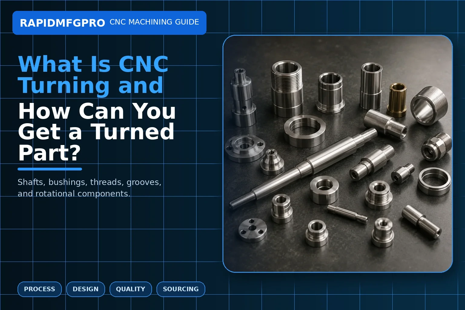
Direct answer: CNC turning is a machining process in which a workpiece rotates while cutting tools remove material. It is the preferred process for parts dominated by concentric diameters, such as shafts, pins, bushings, rings, rollers, spacers, threaded components, and cylindrical housings. To get a turned part, provide a 3D model and controlled drawing that define material, diameters, lengths, fits, threads, runout, surface finish, quantity, and inspection needs. The supplier then selects stock, develops a turning program, machines a first article, inspects it, and releases the batch.
Turning looks simple because many parts appear rotationally symmetric, but accurate turning requires control of workholding, tool pressure, heat, bar straightness, parting, and datum transfer. A long shaft, thin ring, deep internal bore, or tight bearing fit can be much more difficult than a short thick spacer. This guide explains how CNC turning works and how RapidMfgPro helps buyers identify independent turning suppliers whose equipment and process experience fit the actual part.
What Is CNC Turning?
The workpiece rotates around a spindle axis
In CNC turning, bar stock, tube, billet, forging, or a near-net-shape blank is held in a chuck, collet, or between centers. The spindle rotates the workpiece while a stationary or controlled cutting tool moves along the machine axes. The cutting edge removes material from the outside diameter, face, inside diameter, groove, or thread.
Because the part rotates, turning naturally creates cylindrical and conical surfaces that share an axis. This makes it efficient for concentric features. A single setup can machine multiple diameters, shoulders, grooves, tapers, bores, and threads while preserving their relationship to the spindle axis.
CNC turning differs from manual lathe work because the tool motions, spindle speed, feed rate, and operation sequence are controlled by a program. Skilled operators remain essential for setup, tool selection, offset control, chip management, and inspection.
Modern turning centers can do more than round shapes
A basic two-axis lathe controls movement along X and Z. More advanced turning centers may include a Y axis, live tooling, sub-spindle, C-axis positioning, or multiple turrets. Live tooling allows drills and end mills to rotate while the main spindle is indexed or synchronized. This makes it possible to add cross holes, flats, keyways, slots, bolt patterns, and off-center features.
A sub-spindle can grip the partially machined part and complete the back side without manual reclamping. Bar feeders support repeated production from long stock. Swiss-type machines guide bar close to the cutting point and are well suited to small, long, slender, or high-volume precision components.
| Turning machine type | Best suited to | Key advantage | Important limitation |
|---|---|---|---|
| 2-axis CNC lathe | Simple shafts, bushings, rings, spacers | Efficient concentric machining | Off-axis features need another setup |
| Turning center with live tooling | Turned parts with flats, cross holes, slots | Completes more features in one machine | Tool access and power may be lower than a dedicated mill |
| Sub-spindle turning center | Parts needing complete front and back machining | Reduces manual reclamping and datum transfer | Part length and gripping area must be planned |
| Swiss-type lathe | Small precision pins, medical parts, connectors | Supports slender parts near the cut | Best economics usually require suitable bar geometry and quantity |
| Vertical turning lathe | Large heavy rings, flanges, hubs | Gravity supports large workpieces | Not intended for small bar-fed parts |
How Does a CNC Turning Project Start?
The supplier reviews the design and stock route
The process begins with a CAD model and drawing. The supplier identifies the primary turning axis, finished diameters, raw stock, gripping length, cut-off allowance, and whether the part can be completed from bar. A hollow part may be more economical from tube, while a flange may start from forged or sawn round stock.
The drawing should define the material grade and condition, not only a broad family. It should also identify critical fits, threads, surface finish, heat treatment, coating, edge breaks, and inspection. A bearing journal may require a specific ISO fit and roughness. A seal diameter may require controlled runout and no spiral tool marks.
Design review should consider tool access to deep bores, minimum wall thickness, groove width, thread relief, and the location of the cut-off face. If the finished part has no safe gripping area, the process may require soft jaws, a sacrificial extension, or a second-operation fixture.
Programming and setup convert requirements into a stable sequence
The programmer selects roughing, finishing, grooving, threading, drilling, boring, and parting tools. Rough turning removes most stock while leaving a finish allowance. Finishing passes establish the final diameter, roundness, and surface. Tool nose radius compensation is important because the programmed path is not the same as the physical cutting edge.
The operator installs the correct chuck or collet, loads stock, sets tools, establishes the coordinate origin, and verifies spindle direction and speed limits. Long bars require proper support and safe spindle-speed limits to prevent whipping. A first article is then machined and measured.
For repeated batches, the supplier should define tool-life controls, offset adjustment rules, and inspection frequency. A diameter may drift as an insert wears, even if the program never changes.
Which Features Can CNC Turning Produce?
External and internal turning create the main geometry
Facing establishes a flat end surface. Outside-diameter turning creates cylindrical surfaces and shoulders. Taper turning creates conical geometry. Boring enlarges and finishes internal diameters. Grooving creates reliefs, seal grooves, snap-ring grooves, and undercuts. Parting separates the finished component from bar stock.
Threads may be cut with a single-point insert, thread-forming tool, tap, die, or thread mill depending on the machine and feature. Single-point turning is flexible for external and internal threads, but the drawing must state the thread standard, pitch, class, hand, engagement length, and any gauge requirement.
Knurling displaces material to create a grip pattern. It is different from cutting and can increase the outside diameter. Engineers should specify pattern, pitch, diameter requirement, and cosmetic acceptance criteria.
Driven tools add non-concentric details
Live tooling can drill holes through the side of a shaft, mill wrench flats, cut keyways, create slots, and machine off-axis patterns. C-axis control positions the spindle angularly. A Y axis improves off-center access and allows more complex milling.
Not every turned-milled part should stay on one machine. A heavy milling feature may be faster on a machining center. The supplier should compare one-machine completion with a lathe-plus-mill route based on total setup time, tolerance transfer, cycle time, and quality risk.
| Part feature | Typical turning operation | Drawing requirement | Frequent problem |
|---|---|---|---|
| Bearing journal | Finish turning or grinding | Fit, roundness, runout, surface roughness | Diameter drift or tool marks |
| Deep internal bore | Drilling then boring | Diameter, depth, straightness, bottom geometry | Bar deflection, chatter, poor chip removal |
| External thread | Single-point threading | Standard, pitch, class, length, relief | Incorrect crest, burrs, coating interference |
| O-ring groove | Grooving tool | Width, depth, radius, finish | Leakage from width or surface errors |
| Thin ring | Turn, part, and finish with special support | Wall thickness, roundness, free-state condition | Distortion after unclamping |
| Cross hole | Live-tool drilling or second operation | Angular position and relation to datums | Position error or drill breakout burr |
When Is CNC Turning the Right Process?
Use turning when most critical geometry shares an axis
If the functional surfaces are diameters, shoulders, tapers, threads, grooves, and bores around a common centerline, turning is usually the most efficient process. Shafts, pins, rollers, nozzles, bushings, spacers, piston-like parts, and circular adapters are typical examples.
Turning often produces better concentric relationships than milling the same cylindrical features because the part rotates around the spindle axis. Multiple diameters can be finished in one clamping. This is valuable for bearing fits, seal diameters, and rotating assemblies.
Use another route when the part is mainly prismatic
A rectangular housing with one circular bore is usually a milling job, even though it contains a round feature. A thin sheet-metal cylinder may be rolled and welded. A very high-volume simple pin may be cold headed or formed. A large near-net-shape flange may be forged or cast before finish turning.
Many parts use both turning and milling. The correct question is not “Is the part round?” but “Which process can create the critical features with the fewest stable setups?”
| Geometry and demand | Turning suitability | Reason | Process to compare |
|---|---|---|---|
| Stepped shaft with bearing fits | Excellent | Diameters and shoulders share one axis | Grinding after turning for very tight finish |
| Flanged bushing with bolt holes | Strong | Turn main body; add holes with live tooling or milling | Mill-turn or two-machine route |
| Rectangular manifold with one bore | Weak as primary process | Most geometry is prismatic | CNC milling |
| 100,000 simple steel pins | Conditional | Turning works, but forming may reduce unit cost | Cold heading or screw-machine process |
| Large heavy ring | Strong | Vertical turning handles size and mass well | Forging plus finish machining |
| Thin decorative tube | Partial | Ends and features can be turned | Tube fabrication plus machining |
How Should You Design a Turned Part?
Provide tool relief and practical feature proportions
Shoulders next to threads or ground diameters often need relief so the tool can exit cleanly. Blind internal threads need runout space. Very narrow grooves require fragile tools and may trap chips. Deep bores require long boring bars that can vibrate.
Use standard thread sizes, groove widths, and radii where possible. Avoid placing many unrelated diameters at extremely tight tolerance. If a shoulder face controls bearing location, specify its relationship to the journal. If a thread only retains a cover, it may not need the same positional control as a rotating seal interface.
Long slender parts may require centers, steady rests, follower rests, or Swiss-type support. The drawing should identify acceptable center marks or support marks if cosmetic requirements matter.
Plan how the part will be held for the second end
A bar-fed part needs a cut-off location. The back face may require a second operation. If the outside diameter is already finished and cosmetic, standard chuck jaws can damage it. Soft jaws, collets, expanding mandrels, or sacrificial gripping diameters may be required.
Designers can make the process easier by leaving a practical gripping feature or defining a surface that may carry minor jaw marks. For high-volume work, a small design change that improves workholding can save substantial cycle time and scrap.
Which Materials Are Commonly Turned?
Metals vary in chip behavior and tool wear
Free-machining steels, brass, and aluminum often produce efficient turning cycles. Aluminum 6061 is common for general-purpose shafts, spacers, and housings. 7075 is used for higher strength. Brass provides good machinability and is used for fittings, valves, and electrical parts.
Stainless steel work-hardens and can produce long chips. 303 is easier to turn than 304, while 316 provides stronger corrosion resistance. Alloy steels may be turned before or after heat treatment depending on dimensional and wear requirements. Titanium and nickel alloys need controlled cutting speed, rigid setups, and careful tool selection.
Plastics need support and temperature control
POM, nylon, PTFE, PEEK, UHMW, and other engineering plastics can be turned into bushings, rollers, seals, insulators, and guides. Plastics can expand from heat and deform under chuck pressure. Thin rings may become oval after release.
Sharp tools, light finishing cuts, soft jaws, and time for dimensional stabilization can improve results. Moisture-sensitive nylon may need conditioning or measurement at a defined state.
How Are Tolerances, Runout, and Surface Finish Controlled?
Datum and clamping choices control concentricity
When several diameters are finished in one setup, their concentric relationship is often strong. Problems arise when the part is flipped, gripped on an imperfect surface, or measured from an unclear datum. Runout should be specified relative to the functional axis or datum feature.
For a shaft with bearing journals at both ends, process planning may involve turning between centers, grinding, or carefully transferred setups. A simple note such as “concentric” is not enough. The drawing should use a measurable geometric control and identify the datum axis.
Surface finish depends on feed, tool geometry, and stability
Turning creates a helical feed pattern. The theoretical roughness depends partly on feed rate and tool nose radius, but real finish also depends on material, insert condition, built-up edge, vibration, and coolant. Seal surfaces may require a defined roughness and restrictions on lead or spiral marks.
Very tight size, roundness, or finish may require grinding, honing, lapping, or superfinishing after turning. The supplier should include these operations in the process plan rather than promise that the lathe alone will always achieve them.
| Critical characteristic | Process control | Inspection method | Common documentation |
|---|---|---|---|
| Outside diameter fit | Finish pass and tool-wear offsets | Micrometer or air gauge | Dimensional report or control chart |
| Internal bore | Rigid boring bar, reaming, or honing | Bore gauge, air gauge, CMM | First article and sampling plan |
| Runout | Machine related features in one setup | Indicator between centers or CMM | Runout result referenced to datum |
| Thread | Controlled insert, offsets, and deburring | GO/NO-GO gauge or thread measurement | Gauge calibration record if required |
| Seal finish | Stable finishing cut or grinding | Roughness tester and visual check | Ra/Rz record and defect criteria |
Do Turned Parts Need Secondary Machining or Finishing?
Heat treatment and grinding may be part of the functional route
Wear-resistant shafts may be turned oversize, heat treated, straightened, and ground to final size. Heat treatment can change dimensions and straightness, so machining allowance is essential. A hardened bearing journal may not be reliably finished before heat treatment.
Cross holes, keyways, splines, or complex flats may require milling, broaching, EDM, or grinding. The turning supplier should coordinate datum transfer between processes. Buyers should confirm whether one supplier manages all operations or whether outside processors are used.
Coatings affect fits, threads, and contact surfaces
Black oxide, passivation, plating, anodizing, nitriding, painting, and other finishes may be applied depending on material and application. Coating thickness can change a bearing fit or thread. Masking requirements should be on the drawing.
Deburring and cleaning are particularly important for grooves, threads, cross-hole intersections, and fluid passages. A small burr inside a hydraulic or medical component can cause failure even when the main dimensions are correct.
How Can You Get a CNC-Turned Part through RapidMfgPro?
Prepare a complete request for quotation
Provide the 3D model, 2D drawing, exact material, quantity, finish, heat treatment, target date, inspection needs, destination, and annual demand. For long shafts, include straightness and runout requirements. For threads, identify the standard and gauge class. For seals or bearings, specify fits and surface finish.
Tell RapidMfgPro whether the part can be changed for manufacturability. A small relief, standard groove, or practical gripping extension may reduce risk. If the design is fixed, state that clearly.
Match the part to the right turning supplier
RapidMfgPro can help identify independent suppliers with suitable bar capacity, chuck size, spindle bore, Swiss capability, live tooling, sub-spindle equipment, grinding access, material experience, and inspection resources. The appropriate supplier for 3 mm medical pins is different from the supplier for a 900 mm heavy ring.
Compare quotations based on process route, material source, inspection, secondary operations, lead time, and repeat-production control. RapidMfgPro helps organize the sourcing process, while the buyer approves the technical and commercial arrangement with the selected supplier.
What Common Turned-Part Design Mistakes Cause Problems?
Unrealistic deep bores and unsupported slender sections
A deep bore with a small diameter requires a long boring bar. The bar can deflect and vibrate, causing taper, poor finish, and inconsistent diameter. Designers can reduce risk by increasing bore diameter, shortening depth, allowing a larger bottom radius, or splitting the component. When the feature cannot change, the supplier may need a damped bar, special drill, or honing operation.
Long slender shafts can bend during cutting. A drawing that requires tight straightness after machining should identify whether center holes, steady-rest marks, or grinding are acceptable. Material condition and heat treatment must also be included because a shaft may move after hardening.
Missing thread relief, grinding allowance, or gripping area
Threads need lead-in and runout space. Ground journals need stock allowance. A second operation needs a safe surface to grip. If the design consumes every surface with final geometry, the supplier may add sacrificial stock or develop costly custom workholding.
These issues are easiest to resolve during DFM review. A small undercut, extension, or tolerance change may reduce tool risk without affecting function. Any approved change should be incorporated into the controlled model and drawing.
How Do You Move from a Turned Prototype to Repeat Production?
Validate the first article using the intended production route
The first article should confirm material, program, tools, workholding, secondary operations, inspection, and packaging. If the prototype is hand-finished but the production batch will use automated bar feeding and a sub-spindle, the process is not fully validated. Critical features should be produced with the planned route whenever practical.
Review measurement data, thread gauges, runout, surface finish, heat-treatment certificates, and assembly fit. Record any offset or process adjustments made during approval.
Control tool wear, bar stock, and batch consistency
For repeated production, define tool-change limits, sampling frequency, bar-lot traceability, and reaction plans. Collets and guide bushings wear. Long bar stock can vary in straightness. Chips can wrap around tools and change surface condition. These risks should be managed rather than left to operator judgment alone.
Ask the supplier how programs, setup sheets, jaws, and gauges are preserved between orders. RapidMfgPro can help compare suppliers on repeat-production control, not only prototype responsiveness.
What Should Be Included in a Turned-Part RFQ?
Define every rotational interface in the final condition
List the exact material grade and condition, raw-stock preference if important, finished diameters, lengths, fits, shoulders, tapers, grooves, threads, runout, straightness, surface finish, heat treatment, and coating. Identify which dimensions apply after grinding or plating. For a shaft, show the bearing and seal locations and identify the datum axis. For a bushing, define both the bore fit and the outside-diameter relationship.
Include section views for deep bores and blind internal features. State whether center holes, chuck marks, or witness marks are acceptable. If the part must be made from a sample, identify worn surfaces and provide assembly measurements rather than assuming the sample represents nominal geometry.
Include quantity, repeat demand, and inspection evidence
State prototype quantity, expected batch size, annual volume, delivery location, and target date. These details influence whether the supplier uses manual chucking, collets, bar feeding, Swiss turning, a sub-spindle, or dedicated gauges. Request the appropriate evidence: material certificate, first article, thread-gauge result, runout report, hardness certificate, or complete dimensional report.
A structured RFQ also helps RapidMfgPro compare independent turning suppliers on the same basis. It reduces the chance that one quotation includes grinding and certification while another covers only rough turning.
Conclusion
CNC turning is the most efficient choice when a part’s critical geometry is organized around a common axis. It can produce shafts, pins, bushings, rings, threads, grooves, and complex mill-turn components with strong concentric control. Reliable results depend on stock selection, workholding, relief design, tool-wear control, and inspection of fits, runout, and finish. A complete CAD and drawing package allows RapidMfgPro to identify independent turning suppliers whose machines and process experience fit the part size, complexity, quantity, and quality risk.
Need Help Reviewing a Custom Part?
Share your CAD file and requirements to request supplier matching. Supplier capability and commercial terms must be verified before order placement.
Request Supplier Match