Time to read: 8 min
What Is First Article Inspection? Why Is It Important Before CNC Part Production?
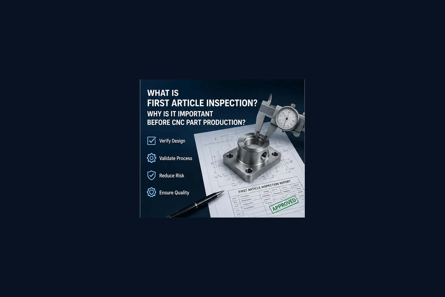
First Article Inspection, commonly shortened to FAI, is a structured verification process used to confirm that a CNC part produced by the intended manufacturing route meets the released engineering requirements. It checks more than whether one sample looks correct. A complete FAI links the part number, drawing revision, material, dimensions, geometric tolerances, special processes, surface treatments, markings, test results, and supporting certificates to a specific production-representative part or batch.
FAI is important before CNC part production because many problems cannot be detected by reviewing a quotation, CAD model, or machining simulation. The drawing may contain conflicting dimensions, the chosen datum may be difficult to inspect, a plated thread may become too tight, heat treatment may distort a bore, or the supplier may misunderstand a note that affects assembly. FAI exposes these issues before they are repeated across a larger production lot.
FAI should not be confused with simply checking the first part removed from a machine. A first-off inspection may verify several setup dimensions so production can continue, while a formal FAI typically verifies the complete engineering definition and the associated manufacturing evidence. It also does not replace process capability studies, ongoing production inspection, or functional validation. An approved first article proves that the defined process produced at least one conforming result; production controls are still required to maintain that result.
RapidMFGPro evaluates FAI requirements from a supplier-matching perspective. The review considers drawing complexity, material, tolerance, special processes, inspection equipment, documentation, quantity, industry expectations, and production schedule before identifying suppliers whose machining, metrology, traceability, and quality systems fit the project.
This guide explains what First Article Inspection is, what should be included, when it should be repeated, how it is performed, and why it is an important quality gate before CNC part production.
What Does First Article Inspection Verify?
FAI verifies that the released engineering definition has been translated into a complete and controlled manufacturing result.
Product Definition
The inspection confirms that the part matches the approved drawing, 3D model, specifications, and revision.
This prevents obsolete or incomplete files from entering production.
Material Requirement
The material grade, temper, hardness, product form, and required certification are checked.
Generic similarity is not enough when the drawing requires an exact alloy or condition.
Dimensional Requirement
Dimensions, tolerances, threads, fits, hole sizes, wall thicknesses, and geometric controls are verified.
Final measurements should represent the completed part condition.
Process Requirement
Heat treatment, plating, anodizing, passivation, welding, coating, cleaning, marking, and other specified processes are confirmed through records and inspection.
A dimensionally correct part can still fail if a required process is missing or incorrect.
| Verification Area | Typical Evidence | Common Risk if Missing |
|---|---|---|
| Drawing revision | Controlled drawing and model | Production to an obsolete design |
| Material | Certificate and lot identification | Wrong alloy, temper, or hardness |
| Dimensions and GD&T | Inspection report and measured results | Assembly, alignment, or sealing failure |
| Special processes | Heat-treatment or coating certificate | Incorrect mechanical or surface performance |
| Marking and packaging | Visual record and packing check | Traceability loss or transport damage |
Why Is FAI Important before Production?
FAI prevents a single engineering or process misunderstanding from being multiplied across a production order.
It Detects Drawing Interpretation Problems
Different suppliers may interpret datums, coating notes, thread callouts, or inspection conditions differently.
FAI creates a documented opportunity to align those interpretations.
It Confirms the Complete Process Route
Machining, heat treatment, finishing, cleaning, and inspection may each change the final part.
FAI verifies the completed route rather than only the machined blank.
It Reduces Large-Lot Risk
Correcting five first-article parts is less expensive than sorting or scrapping five hundred production parts.
Early verification limits the financial impact of hidden problems.
It Establishes a Quality Baseline
The approved first article and report provide a reference for future production, change review, and supplier comparison.
The baseline helps distinguish approved variation from an uncontrolled process change.
Is FAI the Same as Inspecting the First Part?
FAI and first-part inspection are related, but they do not normally have the same scope.
First-Off Inspection
A first-off inspection checks selected dimensions after a setup, tool change, or process start.
It helps release the machine to continue production.
Formal FAI
A formal FAI verifies the complete part definition and supporting documentation.
It may include every drawing characteristic, material record, and special-process requirement.
Production Inspection
Production inspection monitors the process after FAI approval.
Sampling, in-process checks, control charts, and functional gauges maintain continued conformity.
Different Quality Questions
First-off inspection asks whether a setup can begin producing. FAI asks whether the production-intent process has produced a part that satisfies the complete released definition.
Is FAI the Same as PPAP?
FAI and Production Part Approval Process are not the same, although both support production approval.
FAI Focus
FAI focuses on verifying the part and its engineering characteristics.
It is common in aerospace, defense, precision machining, and custom industrial production.
PPAP Focus
PPAP generally includes broader process-approval evidence such as process flow, risk analysis, control plans, measurement studies, capability data, and production samples.
It is strongly associated with automotive and high-volume supply chains.
Possible Overlap
Dimensional results, material records, special-process evidence, and approved samples may appear in both packages.
The customer should define which approval method is required.
What Does FAI Not Prove?
FAI is an important quality gate, but it does not prove every future production part will conform.
It Does Not Prove Long-Term Capability
One conforming article does not represent tool wear, machine drift, operator changes, or material-lot variation.
Capability studies and production data are still needed.
It Does Not Replace Functional Testing
A dimensionally conforming part may still fail pressure, fatigue, electrical, thermal, or assembly tests.
Required functional validation should remain separate.
It Does Not Approve Uncontrolled Changes
Changing material, machine, supplier, process route, or drawing revision can invalidate the original result.
Change control and re-FAI rules are necessary.
It Does Not Eliminate Production Inspection
Ongoing controls are required to detect drift after approval.
FAI establishes the starting point rather than the entire control system.
When Is a Full FAI Required?
A full FAI is commonly required before the first production release of a new part or manufacturing route.
New Part Number
A newly released CNC part usually requires complete verification before normal production.
The requirement should be included in the RFQ and purchase order.
New Supplier
A new supplier uses different machines, fixtures, tools, programs, inspection systems, and special-process sources.
The original supplier’s FAI does not automatically approve the new process.
New Manufacturing Location
Moving production to another facility changes equipment, environment, personnel, and quality controls.
The level of revalidation should be defined.
Major Process Change
A new manufacturing route, heat treatment, coating system, or machining method can justify a full FAI.
The decision depends on how much of the original process has changed.
When Is a Partial FAI Appropriate?
A partial FAI verifies only the characteristics affected by an approved change while retaining valid evidence from the previous inspection.
Drawing Revision
When only selected dimensions or notes change, the affected features can be reinspected.
Unchanged characteristics may remain valid if the process is unchanged.
Tooling Change
A new fixture, form tool, or cutting method may affect a limited group of dimensions.
The affected characteristics should be identified before inspection.
Special-Process Change
A new plating or heat-treatment supplier may require verification of thickness, hardness, dimensions, adhesion, color, or performance.
Unaffected machined features may not need complete remeasurement.
Documented Rationale
The partial scope should explain what changed, which characteristics are affected, and why other evidence remains valid.
What Changes Commonly Trigger Re-FAI?
Re-FAI is commonly triggered when a change can affect form, fit, function, material, process, or verification.
Design Revision
Changed dimensions, tolerances, materials, finishes, notes, or datums require review.
The re-FAI scope should follow the actual impact.
Machine or Equipment Change
Moving critical features to another machine can change accuracy, thermal behavior, and surface finish.
Related characteristics should be revalidated.
Fixture or Program Change
New clamping, datum transfer, toolpaths, or offsets can change position and deformation.
The revised setup should be inspected before full release.
Long Production Interruption
A long gap may involve lost tooling, different operators, replaced machines, or changed material sources.
Customer or industry requirements may call for re-FAI after an interruption.
What Information Is Needed before FAI Begins?
FAI preparation begins with a complete and controlled technical package.
Released Drawing
The drawing should include part number, revision, dimensions, GD&T, notes, material, and finishing requirements.
Draft drawings should not be used for final approval.
Released 3D Model
The model supports programming and complex-profile inspection.
Model and drawing revisions must agree.
Referenced Specifications
Material, heat treatment, plating, cleaning, testing, marking, and packaging specifications should be available.
Missing references create incomplete inspection.
Customer-Specific Requirements
Reporting format, sampling, approved laboratories, serialization, and documentation rules should be clarified.
The supplier should know these expectations before quotation.
How Is the Drawing Prepared for FAI?
The drawing is commonly converted into a characteristic list so every requirement can be verified systematically.
Balloon the Drawing
Each dimension, tolerance, note, and applicable requirement receives a unique characteristic number.
The numbers link the drawing to the inspection report.
Include Drawing Notes
Surface finish, deburring, heat treatment, marking, cleaning, and coating notes should be ballooned when they require evidence.
Notes should not be ignored because they are not linear dimensions.
Identify Reference Dimensions
Reference dimensions may not require acceptance measurement unless the customer requests them.
Their treatment should be consistent across the report.
Resolve Duplicate Characteristics
Repeated hole patterns or common notes may be grouped or listed individually according to reporting requirements.
The chosen method should remain traceable.
How Should Characteristics Be Classified?
Classifying characteristics helps define inspection method, frequency, and risk.
Critical Characteristics
Critical characteristics can affect safety, regulatory compliance, or catastrophic failure.
They may require additional traceability and control.
Key Characteristics
Key characteristics significantly affect fit, function, performance, or production variation.
Capability monitoring may be required after FAI.
Standard Characteristics
Standard characteristics still require conformity but may use routine inspection methods.
Their production sampling can be based on process risk.
Cosmetic Characteristics
Color, texture, scratches, dents, and visible tool marks require defined zones and viewing conditions.
Approved samples can support objective acceptance.
How Should the FAI Part Be Selected?
The FAI part should represent the intended production process rather than a specially corrected sample.
Production-Intent Material
The part should use the specified material grade, temper, and product form.
Substitute prototype material does not validate production.
Production-Intent Equipment
The intended machine type, fixture, tools, program, and special-process route should be used.
Laboratory-only processing should be disclosed.
Representative Fixture Position
Multi-position fixtures may require parts from more than one cavity or station.
The selected article should not hide position-to-position variation.
No Unapproved Manual Correction
Hand fitting, selective polishing, straightening, or special rework should be documented.
A corrected part may not represent production capability.
How Many Parts Should Be Inspected?
Formal FAI may be based on one representative article, but additional samples are often needed to evaluate repeatability and different process conditions.
One Complete Article
One article can provide full dimensional and documentation evidence.
It does not demonstrate statistical capability.
Multiple Fixture Positions
Each cavity or fixture station may require selected verification.
Position-specific errors can otherwise remain hidden.
Destructive Tests
Hardness cross-sections, coating sections, tensile tests, and metallography may require separate specimens or coupons.
The tested sample should remain linked to the production lot.
Pilot-Batch Support
Additional pilot parts can be measured for capability and assembly validation.
This supplements rather than replaces the full FAI.
What Material Evidence Should Be Included?
Material evidence confirms that the physical part was made from the specified material and condition.
Material Certificate
The certificate should identify grade, specification, heat or lot, chemical composition, and mechanical properties as required.
The report should be traceable to the inspected part.
Material Identification
Positive material identification may be used for alloys where mix-up risk is significant.
The method and acceptance limits should match the material.
Hardness Verification
Heat-treated metals and selected plastics may require hardness testing.
Test location and method should not damage a critical surface.
Product Form and Temper
Plate, bar, extrusion, forging, casting, and molded stock should match the requirement.
Product form can affect residual stress and performance.
How Are Dimensional Characteristics Inspected?
Each dimensional characteristic should use a measurement method appropriate for the tolerance, geometry, surface, and access.
Linear Dimensions
Calipers, micrometers, height gauges, CMMs, and optical systems can measure lengths, thicknesses, and distances.
The instrument uncertainty should be small relative to the tolerance.
Hole and Bore Sizes
Plug gauges, bore gauges, air gauges, CMMs, and internal micrometers may be used.
Taper, ovality, and depth should be considered.
Shaft Diameters
Micrometers, snap gauges, air gauges, and roundness equipment can verify external diameters.
Measurements should cover the functional length.
Wall Thickness
Micrometers, CMMs, ultrasonic methods, or section measurements may be required.
Flexible walls should not be compressed by the gauge.
How Are GD&T Characteristics Inspected?
Geometric tolerances require correct datum simulation and sufficient measurement coverage.
Position
CMMs, vision systems, and functional gauges can verify hole and feature location.
Datum references and material-condition modifiers must be applied correctly.
Profile
CMM scanning, optical scanning, and dedicated fixtures can evaluate complex surface deviation.
Point density and alignment method affect the result.
Flatness
Surface plates, indicators, CMMs, and optical systems can measure flatness.
Flexible parts should not be forced flat during inspection.
Runout
Rotational fixtures, indicators, roundness machines, and CMMs can evaluate circular or total runout.
The datum axis should represent the functional rotation.
How Are Threads Inspected during FAI?
Thread inspection should confirm form, size, position, depth, orientation, and final coating condition.
Internal Threads
Go/No-Go plug gauges are commonly used for internal threads.
Thread depth and incomplete-thread zones may require separate checks.
External Threads
Ring gauges, thread micrometers, and optical methods can verify external threads.
Plating and coating thickness should be included.
Thread Position
Thread size conformity does not prove correct location or perpendicularity.
Datum-based positional inspection may also be required.
Functional Assembly
Mating fasteners or components can confirm final assembly.
Functional testing should use the specified class and coating.
How Are Surface-Finish Requirements Verified?
Surface-finish verification should distinguish roughness, waviness, lay, texture, and cosmetic appearance.
Roughness Measurement
Contact profilometers and optical systems can measure Ra and other parameters.
Cutoff length and measurement direction should be appropriate.
Lay Direction
Turning, grinding, milling, and honing create directional texture.
Lay can affect sealing, friction, and appearance.
Cosmetic Comparison
Approved samples, controlled lighting, and defined viewing distance can be used.
Cosmetic inspection should identify visible and hidden zones.
Post-Finish Surface
Anodizing, plating, blasting, polishing, and coating can change the final texture.
Inspection should occur after the last relevant process.
How Are Heat-Treatment Requirements Verified?
Heat-treatment verification confirms both process completion and final material condition.
Process Certificate
The certificate should identify part lot, specification, cycle, and acceptance as required.
Traceability should connect the certificate to the inspected article.
Hardness Test
Surface or core hardness may be measured using the specified scale and location.
Thin sections and coatings require suitable test loads.
Case Depth
Carburized, nitrided, or induction-hardened parts may require case-depth verification.
This often uses destructive sectioning or representative coupons.
Distortion Check
Bores, flatness, runout, and straightness should be checked after heat treatment.
Pre-treatment dimensions do not prove final conformity.
How Are Surface Treatments Verified?
Surface-treatment verification should confirm coating type, thickness, coverage, masking, adhesion, appearance, and final dimensions.
Anodizing
Type, thickness, color, sealing, masking, and final thread or bore dimensions may require verification.
Alloy variation should be considered for appearance.
Electroless Nickel
Phosphorus range, thickness, hardness, heat treatment, adhesion, and masking may be required.
Multilayer or post-ground dimensions should be recorded in the final condition.
Zinc or Tin Plating
Thickness, passivation, solderability, baking, friction, and final thread fit may be checked.
High-strength steel may require hydrogen-relief evidence.
Paint and Powder Coating
Resin system, color, gloss, film thickness, cure, adhesion, masking, and appearance should be verified.
Precision interfaces are normally checked after masking removal.
How Are Welded and Assembled Parts Verified?
CNC-machined assemblies may include welding, brazing, inserts, fasteners, adhesives, and press fits that require evidence beyond individual component dimensions.
Weld Geometry
Weld size, location, penetration, distortion, and appearance may be checked.
Nondestructive testing may be required for critical joints.
Inserted Hardware
Threaded inserts, bushings, pins, and press-fit hardware should be checked for location, retention, and damage.
Installation can change the surrounding dimensions.
Fastened Assemblies
Torque, orientation, locking method, and final alignment should be confirmed.
Loose or over-tightened hardware can invalidate dimensional results.
Adhesive Bonding
Adhesive type, batch, surface preparation, cure, bond line, and handling may require traceability.
Destructive bond testing can use representative coupons.
How Are Functional Requirements Verified?
Some drawing requirements can only be verified through functional testing.
Leak Testing
Manifolds, valves, housings, and cold plates may require pressure, vacuum, or helium leak testing.
Test pressure, duration, medium, and acceptance should be defined.
Electrical Testing
Resistance, continuity, insulation, grounding, or temperature-rise tests may be required.
Surface treatment and assembly pressure influence results.
Motion Testing
Sliding force, bearing rotation, runout, backlash, and actuator movement can be verified.
The test should use representative mating components.
Load Testing
Fixtures, brackets, joints, and structural parts may require proof load or torque testing.
Destructive and nondestructive limits should be distinguished.
How Are Marking and Identification Verified?
Marking supports traceability, assembly, service, and regulatory compliance.
Part Number and Revision
Marking should match the released definition and remain readable after finishing.
Obsolete revision marks create serious traceability risk.
Serial and Lot Numbers
Serialization may link the part to material and process records.
Number format and location should be controlled.
Marking Method
Laser marking, engraving, stamping, ink, and labels affect the surface differently.
The method should not damage fatigue-critical or sealing areas.
Legibility and Durability
Contrast, size, depth, adhesion, and resistance to cleaning or abrasion may be checked.
Marking should remain visible for the intended service life.
How Is Cleanliness Verified?
Cleanliness can be a functional requirement for fluid, medical, vacuum, optical, and electronic components.
Visual Cleanliness
Visual checks identify chips, oil, dust, stains, fibers, and residue.
Hidden passages may require borescopes or flushing.
Particle Cleanliness
Parts may be flushed and the extracted particles counted or weighed.
Limits should identify particle size and total contamination.
Oil-Free Requirement
Water-break, solvent extraction, or other tests may be used.
Handling and packaging must preserve the cleaned state.
Internal Passage Verification
Manifolds, cold plates, and valves can retain chips or process chemicals.
Final cleaning should occur after all operations that generate contamination.
How Is Packaging Included in FAI?
Packaging is part of the delivered-product condition and can be included in first-article approval.
Part Protection
Trays, bags, caps, dividers, foam, and films should prevent scratches, dents, bending, and contamination.
Packaging materials should be compatible with the finish.
Quantity and Orientation
Quantity per container and loading orientation should be defined.
Heavy parts should not shift or crush thin components.
Labeling
Labels should identify part number, revision, lot, quantity, and status.
Customer-specific barcode or shipment data may be required.
Transport Validation
Drop, vibration, compression, moisture, or route testing may be appropriate.
A conforming part must arrive in the same condition in which it was accepted.
What Should an FAI Report Contain?
The report should provide traceable evidence that every required characteristic was reviewed and accepted.
Part and Revision Information
Include part number, name, drawing revision, inspection date, supplier, and manufacturing lot.
The data should identify the exact article.
Characteristic Results
List each balloon number, requirement, measured result, inspection method, and acceptance status as required.
Pass statements should not replace actual results where measured data is required.
Material and Process Records
Attach or reference certificates for material, heat treatment, plating, coating, testing, and other special processes.
The records should be legible and lot specific.
Approval and Deviation Status
Identify open nonconformities, approved deviations, rework, or customer concessions.
Conditional approval should not be presented as unconditional acceptance.
| Document | Purpose | Key Traceability |
|---|---|---|
| Ballooned drawing | Identifies every characteristic | Drawing number and revision |
| Dimensional report | Records requirements and results | Characteristic and instrument reference |
| Material certificate | Confirms alloy and condition | Heat or material lot |
| Special-process certificates | Confirms heat treatment and finishing | Process lot and supplier |
| Functional test results | Confirms performance requirements | Test method and tested article |
| Approval record | Documents release or deviation | Approver and date |
Should Actual Measurement Results Be Reported?
Actual results provide stronger evidence than a simple pass statement and help evaluate process margin.
Measured Values
Recording actual values shows how close the part is to the limits.
This supports production planning and capability review.
Attribute Results
Some requirements are appropriately recorded as pass or fail, such as a Go/No-Go gauge or visual marking check.
The inspection method should still be identified.
Calculated Results
Position, profile, runout, and other geometric values may be calculated by software.
Datum alignment and evaluation method should be controlled.
Out-of-Tolerance Results
Results should not be rounded or omitted to create an apparent pass.
Nonconformities require documented disposition.
How Should Measurement Equipment Be Selected?
The measurement system should be appropriate for the tolerance and feature.
Resolution
The instrument should display changes small enough to evaluate the tolerance reliably.
Resolution alone does not guarantee accuracy.
Measurement Uncertainty
Calibration, environment, fixture, operator, software, and method contribute to uncertainty.
Narrow tolerances require lower uncertainty.
Contact Force
Flexible walls, soft copper, plastics, seals, and coatings can deform under measurement force.
Low-force or noncontact methods may be preferable.
Feature Accessibility
Deep holes, undercuts, internal channels, and small slots may need special probes, replicas, or destructive sections.
Inspection feasibility should be reviewed during design.
How Should Calibration Be Verified?
FAI results are trustworthy only when the measurement equipment is calibrated and controlled.
Calibration Status
The instrument should be within its approved calibration period.
Expired or damaged equipment should not be used.
Traceability
Calibration should be traceable to recognized standards where required.
Customer or industry requirements may define the acceptable chain.
Daily Verification
Master parts, gauge blocks, rings, pins, and check standards can verify the instrument before use.
Daily checks do not replace formal calibration.
Out-of-Calibration Review
If a gauge is later found out of calibration, previous inspection results may require review.
The affected time period and parts should be identified.
How Should Measurement Disagreement Be Resolved?
Supplier and customer measurements can disagree because of temperature, datum setup, equipment, software, contact force, or interpretation.
Compare the Drawing Interpretation
Confirm the same datum reference frame, modifiers, and final condition were used.
Interpretation differences should be resolved before remeasurement.
Compare the Measurement Method
A CMM, functional gauge, micrometer, and optical scanner may produce different results.
The approved acceptance method should have priority.
Stabilize the Part
Temperature, cleanliness, and restraint should be consistent.
Flexible parts may need a defined inspection fixture.
Use an Independent Laboratory
A qualified independent laboratory can resolve high-value or technically complex disagreements.
The test scope should be agreed by both parties.
What Happens When the First Article Fails?
A failed FAI should trigger containment, technical review, correction, and reinspection before production release.
Contain the Parts
First articles and any related production should be identified and segregated.
Shipment should not continue without approval.
Identify the Failure Source
The issue may come from the drawing, material, fixture, program, tool, heat treatment, coating, measurement, or handling.
The cause should be investigated rather than assumed.
Correct the Process
Program offsets, fixture design, toolpath, inspection method, masking, or supplier instructions may need revision.
Corrections should be documented.
Repeat the Affected Inspection
The corrected part should be reinspected for the failed and related characteristics.
A full or partial re-FAI may be appropriate.
How Are Deviations Handled?
A deviation is formal authorization to accept or use a part that does not fully meet the released requirement.
Technical Evaluation
Engineering should determine whether the nonconformance affects fit, function, safety, reliability, or appearance.
Purchasing personnel should not approve technical deviations alone.
Defined Scope
The deviation should identify the exact part, lot, quantity, characteristic, and allowed condition.
Broad or permanent wording should be avoided.
Expiration
Temporary deviations should include an end date, quantity limit, or revision condition.
The supplier should return to the released requirement.
FAI Status
A deviated first article may receive conditional approval rather than full conformity approval.
The final record should show the true status.
How Are Reworked First Articles Controlled?
Rework can correct a nonconforming part, but it may not demonstrate the natural production process.
Document the Rework
Record the method, responsible personnel, affected features, and approval.
Undocumented hand correction should not be hidden.
Inspect Related Features
Reaming a bore can change position, finish, wall thickness, or perpendicularity.
Related characteristics should be rechecked.
Review Production Feasibility
A reworked first article may be acceptable for delivery but unsuitable as production evidence.
The process should be corrected and another representative part may be required.
How Long Does FAI Take?
FAI lead time depends on drawing complexity, characteristic count, special processes, inspection equipment, documentation, and customer review.
Simple Turned Parts
A simple shaft or spacer with limited features can be inspected quickly.
Material and plating certificates may still affect completion time.
Complex Milled Parts
Multi-face housings, tight GD&T, deep features, and large characteristic counts require longer CMM programming and inspection.
Complex profile analysis also adds time.
Special-Process Delay
Heat treatment, coating, laboratory tests, and destructive sections can extend the schedule.
The FAI plan should be included in the project timeline.
Customer Approval Time
Production release may depend on customer review and questions.
Complete and organized documentation reduces delay.
What Determines FAI Cost?
FAI cost is driven by inspection effort, documentation, testing, and the complexity of proving conformity.
Characteristic Count
More drawing characteristics require more measurement, recording, and review.
Redundant requirements increase cost without adding quality.
Measurement Method
CMM scanning, roundness testing, air gauging, profilometry, and optical inspection require specialized equipment.
Custom fixtures and probes add setup cost.
Destructive Testing
Metallography, coating sections, tensile tests, and case-depth checks consume samples and laboratory time.
Additional parts may be required.
Documentation Requirements
Ballooned drawings, certificates, photographs, traceability, and customer formats require engineering and quality labor.
Reporting scope should be clear before quotation.
How Can FAI Cost Be Reduced?
FAI cost can be reduced by improving drawing clarity, eliminating redundant controls, planning measurement access, and defining the reporting scope early.
Use Clear Functional Drawings
Consistent datums and nonconflicting tolerances reduce interpretation and reinspection.
Unnecessary tight tolerances should be removed.
Provide Native CAD Data
Controlled 3D models simplify CMM programming and profile comparison.
Model revision must match the drawing.
Define Required Evidence
State whether actual values, certificates, photographs, capability data, or functional tests are required.
Avoid requesting unused documents.
Plan Inspection Features
Accessible datums and measurement surfaces reduce custom fixture and destructive-inspection cost.
Inspection should be considered during part design.
How Does FAI Differ for CNC-Turned Parts?
Turned parts often emphasize diameter, runout, concentricity, thread fit, surface finish, and axial relationships.
Concentric Diameters
Diameters machined in one setup can be verified for runout and coaxial relationships.
Re-chucked features may need separate datum review.
Long Shafts
Straightness, taper, and thermal condition are important for long slender parts.
Measurement support should not bend the shaft.
Threads and Grooves
Thread gauges, pitch diameter, relief, groove width, and location may be required.
Coating can change the final fit.
Surface Finish
Bearing, sealing, and sliding diameters may require profilometer results.
Turning lay direction should match function.
How Does FAI Differ for CNC-Milled Parts?
Milled parts often emphasize datum relationships, hole patterns, profiles, flatness, perpendicularity, pocket depth, and multi-face geometry.
Datum Structure
The FAI should confirm that the inspection frame matches the functional mounting surfaces.
Multiple setups can create datum-transfer error.
Hole Patterns
Position, size, depth, thread, and pattern relationships should be verified.
Functional gauges may supplement CMM data.
Complex Profiles
Freeform and contoured surfaces may require CMM scanning or optical comparison to the model.
Alignment method should be controlled.
Large Flat Faces
Flatness, parallelism, surface finish, and post-coating distortion may require special fixtures and stabilization.
How Does FAI Differ for Thin-Wall Parts?
Thin-wall parts require careful control of measurement force, free-state condition, fixture restraint, and post-process deformation.
Free-State Inspection
The part may need to be measured without external force.
The drawing should define the condition.
Restrained-State Inspection
Flexible parts may be inspected in an assembly-representative fixture.
Restraint points and force should be controlled.
Noncontact Measurement
Optical scanning and low-force probing reduce measurement-induced deformation.
Surface reflectivity and scan alignment require attention.
Packaging Check
Thin-wall parts can pass FAI and deform during shipping.
Packaging should be included in the approval scope.
How Does FAI Differ for Plated Parts?
Plated parts require separate control of the substrate, underplate, topcoat, masking, and final dimensions.
Coating Stack
Tin over nickel, silver over nickel, electroless nickel, zinc passivation, and other stacks should be clearly identified.
Each layer may require thickness evidence.
Final Fits
Threads, bores, shafts, and press fits should be inspected after plating.
Pre-plate conformity does not prove final assembly.
Masking Boundaries
Selective areas, transitions, rack marks, and exposed substrate should be verified.
The drawing should define acceptable locations.
Adhesion and Porosity
Adhesion, porosity, hardness, corrosion, or solderability testing may be required.
Representative coupons should be traceable to the lot.
How Does FAI Differ for Painted or Powder-Coated Parts?
Organic-coated parts require verification of appearance, film thickness, cure, adhesion, masking, and final dimensions.
Color and Gloss
Approved standards and samples should define acceptable color and gloss.
Visual conditions should be controlled.
Film Thickness
Coating thickness should be measured on representative surfaces.
Thick film can interfere with small holes and mating features.
Cure Verification
Oven records, solvent rubs, hardness, or other methods may confirm cure.
Heavy parts require actual metal-temperature control.
Masking and Grounding
Threads, electrical contacts, sealing surfaces, and bearing seats should be checked after mask removal.
Raised coating edges can affect assembly.
How Does FAI Support Aerospace CNC Parts?
Aerospace parts often require formal traceability, special-process control, characteristic accountability, and documented approval before production.
Configuration Control
Part number, revision, specifications, and approved changes must remain controlled.
Obsolete configurations create high risk.
Material Traceability
Heat, lot, certificate, and material condition may require complete traceability.
Substitution usually requires approval.
Special-Process Control
Heat treatment, plating, anodizing, welding, and nondestructive testing may require approved suppliers.
Certificates should be included in the package.
Characteristic Accountability
Each drawing requirement should be accounted for through measurement, certificate, or test.
Missing evidence delays approval.
How Does FAI Support Medical Equipment Parts?
Medical equipment parts can require strong material, cleanliness, process, and documentation controls.
Material and Biocompatibility Inputs
Material grade and finish should match the approved device design.
FAI does not replace application-specific biological or regulatory testing.
Cleanliness
Chips, oils, particles, and process residue may require controlled cleaning and packaging.
Internal passages deserve special attention.
Traceability
Material, process lot, inspection, and marking records may need to remain linked.
Documentation should match the quality system.
Assembly Function
Instrument alignment, motion, sealing, and repeated cleaning may require functional verification.
Cosmetic acceptance alone is insufficient.
How Does FAI Support Automotive and EV Parts?
Automotive and EV components often combine dimensional approval with broader process and performance validation.
High-Volume Readiness
FAI confirms the part definition, while capability and control-plan data support sustained volume.
The complete approval requirement should be clarified.
Battery Components
Busbars, cooling plates, housings, and terminals may require electrical, leak, coating, and cleanliness checks.
Plating and insulation affect final function.
Assembly Gauges
Functional gauges can verify connector, mounting, and hole-pattern interfaces quickly.
Gauge approval and calibration remain important.
Change Management
Material, tooling, location, or supplier changes may require customer notification and reapproval.
Requirements should be agreed before production.
How Does FAI Support Optical and Robotics Parts?
Optical and robotic assemblies depend on precise datum relationships, motion interfaces, and stable lightweight structures.
Optical Alignment
Lens mounts, detector housings, and optical bases may require position, tilt, runout, and surface control.
Assembly-representative datums are essential.
Robotic Joints
Bearing bores, gear interfaces, shafts, and dowel locations affect motion and repeatability.
Functional rotation or backlash tests may be useful.
Lightweight Housings
Thin-wall aluminum and magnesium parts can move during machining, coating, and inspection.
Free-state requirements and packaging should be controlled.
Cosmetic Surfaces
Visible anodizing, blasting, and painting may require approved samples.
Production material and finish should match the FAI article.
How Should Suppliers Prepare for FAI?
Suppliers should plan FAI before machining begins rather than assemble the documentation after the part is finished.
Perform Contract Review
Review every drawing, note, specification, report format, and approval requirement.
Clarify unclear items before production.
Create the Characteristic List
Balloon the drawing and assign inspection methods to each characteristic.
Missing measurement capability should be identified early.
Plan Special-Process Evidence
Confirm that outside suppliers can provide the required certificates and tests.
Process lots should remain traceable.
Reserve Inspection Capacity
CMM programming, laboratory testing, and customer-report preparation require time.
Inspection should be included in the production schedule.
How Should Buyers Review an FAI Package?
Buyers and quality teams should review the package for completeness, traceability, conformity, and unresolved risk.
Check Revision Consistency
Drawing, report, model, certificate, and purchase order should reference the correct part revision.
Mixed revisions should be rejected for clarification.
Check Characteristic Completeness
Every ballooned requirement should have a corresponding result or evidence.
Blank rows and generic passes should be questioned.
Check Traceability
Material and special-process records should link to the inspected part or lot.
Generic supplier brochures do not provide traceability.
Check Open Deviations
Nonconformities, rework, substitutions, and concessions should be visible.
Approval status should be unambiguous.
What Common FAI Mistakes Cause Delays?
Most FAI delays result from incomplete planning, inconsistent revisions, missing records, or unsuitable inspection methods.
Using the Wrong Drawing Revision
The part may be correct to an obsolete drawing but unacceptable to the current release.
Revision control should be checked before machining.
Inspecting before Final Finishing
Coating, heat treatment, and assembly can change dimensions.
Final-condition requirements should be measured after completion.
Missing Drawing Notes
Deburring, marking, cleaning, hardness, and masking notes are sometimes omitted from the report.
Ballooning should include applicable notes.
Incomplete Certificates
Material or process certificates may lack lot identity, specification, or acceptance data.
Documentation should be reviewed before submission.
Unclear Measurement Methods
Results may be disputed when datum setup or gauge method is not defined.
Inspection planning should precede measurement.
How Does FAI Connect to Production Control?
The FAI results should inform the control plan used after approval.
Identify High-Risk Characteristics
Features close to limits or sensitive to tooling should receive stronger production monitoring.
First-article data helps identify these risks.
Select In-Process Gauges
CMM measurement may be used for FAI while faster bore, air, thread, or functional gauges control production.
Correlation between methods should be established.
Define Sampling Frequency
Sampling should reflect feature criticality, process capability, tool life, and production volume.
Unstable features may require 100 percent inspection.
Establish Reaction Limits
Operators should respond before results cross the specification limit.
Warning limits can prevent nonconforming output.
How Does FAI Connect to Process Capability?
FAI confirms conformity, while capability analysis evaluates whether the process can repeatedly remain within tolerance.
FAI Result
One result shows the actual value for the inspected article.
It does not describe the full variation distribution.
Capability Data
Multiple production measurements are used to calculate spread and centering.
The data should come from a stable representative process.
Measurement-System Study
Gauge repeatability and reproducibility should support confidence in the capability result.
Poor measurement can make a capable process appear unstable.
Production Decision
FAI approval plus acceptable capability provides stronger evidence for production release than either alone.
How Does FAI Connect to Change Control?
The approved FAI defines the configuration and process evidence against which future changes are evaluated.
Approved Baseline
The report identifies the part revision, material, process, supplier, and inspection state.
Future changes can be compared with this baseline.
Impact Assessment
Engineering and quality teams should determine which characteristics may be affected by a change.
The result defines full or partial re-FAI scope.
Supplier Notification
Suppliers should notify customers before changing critical equipment, location, material source, or special process.
Required notification rules should be included in the order.
Record Retention
Original and revised FAI records should remain available for traceability.
Retention time depends on customer and industry requirements.
How Can FAI Improve the Drawing?
FAI often reveals drawing issues that should be corrected before recurring production.
Conflicting Tolerances
Duplicate dimensions and overlapping GD&T can produce contradictory acceptance.
The drawing should be revised rather than relying on supplier interpretation.
Unmeasurable Features
Hidden datums, inaccessible surfaces, and undefined free-state conditions may be difficult to verify.
Inspection access should be improved where practical.
Unnecessary Tight Limits
FAI cost and process difficulty may reveal tolerances that provide no functional benefit.
Engineering can relax them through formal revision.
Incomplete Finish Notes
Coating type, thickness, masking, color, and final dimensions may need clearer definition.
Production should not depend on verbal instructions.
How Does RapidMFGPro Plan an FAI Project?
RapidMFGPro approaches FAI as part of the complete supplier and production-readiness review.
Requirement Review
The review identifies drawing revision, characteristic count, material, special processes, tests, documentation, and approval format.
Missing information is identified before supplier matching.
Inspection-Capability Review
CMM, optical scanning, air gauges, profilometers, hardness testers, coating gauges, and external laboratories are considered.
The supplier should have access to every required method.
Process-Route Review
Machining, heat treatment, finishing, cleaning, assembly, testing, and packaging are reviewed in sequence.
Final inspection should follow the last operation that can affect conformity.
Supplier Matching
Suppliers are compared according to CNC capability, metrology, quality systems, special-process control, documentation, traceability, and capacity.
A supplier suitable for simple prototype inspection may not be suitable for a complete production FAI package.
Submission Review
The final package is checked for revision consistency, complete characteristics, certificates, deviations, and approval status.
The objective is a usable quality record rather than a collection of unrelated documents.
How Should FAI-Capable Suppliers Be Evaluated?
Supplier evaluation should consider both part-making capability and evidence-making capability.
Drawing and GD&T Competence
Engineering and quality personnel should understand datum structures, modifiers, profiles, and fit requirements.
Misinterpretation can create a false inspection result.
Metrology Capability
The supplier should have suitable equipment, software, fixtures, calibration, and trained inspectors.
Outsourced measurement should be disclosed.
Special-Process Control
Heat treatment, plating, coating, welding, and testing suppliers should provide traceable records.
Required approvals should be confirmed.
Document Control
Drawings, programs, reports, and certificates should use controlled revisions.
Mixed or obsolete files create FAI failure.
Response to Nonconformance
The supplier should be able to contain, investigate, correct, and revalidate failed characteristics.
Transparent reporting is essential.
What Should Be Included in an FAI RFQ?
The RFQ should define the FAI scope clearly so suppliers quote the same inspection and documentation effort.
Technical Files
Provide the released model, drawing, revision, and referenced specifications.
State which document controls acceptance.
FAI Scope
State full or partial FAI, number of articles, reporting format, actual-value requirements, and customer review.
Avoid assuming every supplier uses the same definition.
Special Tests
Identify material testing, hardness, coating thickness, leak testing, electrical testing, cleanliness, destructive sections, or functional assembly.
Test quantity and acceptance should be included.
Documentation
State required certificates, photographs, calibration references, traceability, serialization, and submission method.
Documentation affects lead time and price.
Production Release
Clarify whether production can begin before customer approval or must wait for formal release.
This decision affects the delivery schedule.
How Should the FAI Approval Decision Be Made?
Approval should be based on complete and traceable conformity, not simply the presence of an inspection report.
Confirm Configuration
Verify that the inspected part matches the correct part number, drawing revision, model, and specifications.
Configuration error invalidates the result.
Confirm Complete Evidence
Every applicable characteristic should have a result, certificate, or test.
Missing evidence should be resolved before full approval.
Confirm Nonconformance Status
Deviations, rework, and open corrective actions should be identified.
Conditional approval should have clear limits.
Confirm Production Representativeness
The inspected part should use the intended material, process, equipment, and special-process route.
Special manual correction should be reviewed.
Confirm Ongoing Controls
The control plan, gauges, sampling, tool-life controls, and change-notification requirements should support production.
FAI approval should connect to continued quality.
| Decision Question | Evidence Required | Risk if Unresolved |
|---|---|---|
| Was the correct revision used? | Matching drawing, model, and report | Approval of an obsolete design |
| Were all characteristics verified? | Complete balloon and result list | Hidden nonconformity |
| Are material and processes traceable? | Lot-specific certificates | Unknown material or treatment |
| Were deviations resolved? | Approved disposition and scope | Uncontrolled production acceptance |
| Was the process production representative? | Intended equipment and route | False confidence from a special sample |
| Are ongoing controls defined? | Control plan and inspection method | Loss of quality after approval |
Frequently Asked Questions
These questions address common decisions about First Article Inspection for CNC parts.
Does FAI Mean Inspecting Only One Part?
A complete report may focus on one representative article, but additional parts can be required for fixture positions, destructive testing, capability, and assembly validation.
Is FAI Required for Every CNC Order?
Not always. It is commonly required for new parts, new suppliers, major changes, and customer-controlled production releases.
Can Production Start before FAI Approval?
Only when the customer and supplier agree. Starting early creates financial risk if the first article later fails.
Does FAI Include Material Certificates?
It commonly includes or references material and special-process certificates when those requirements apply.
Should Coated Dimensions Be Measured after Finishing?
Yes. Functional dimensions affected by anodizing, plating, paint, or powder coating should be verified in the final condition.
What Is a Partial FAI?
A partial FAI reinspects only the characteristics affected by an approved design or process change.
Does an Approved FAI Guarantee Production Quality?
No. Ongoing process control, tool-life management, sampling, capability monitoring, and change control are still required.
Who Approves the FAI?
Approval responsibility depends on the contract. It may involve the supplier, customer quality team, engineering team, or authorized representative.
Conclusion
First Article Inspection is a structured verification that a production-representative CNC part satisfies the complete released engineering definition. It confirms dimensions, GD&T, material, special processes, finishing, marking, testing, traceability, and documentation before larger production risk is accepted. FAI is not simply checking the first machined piece, and it does not replace process capability or ongoing inspection. RapidMFGPro supports FAI projects by reviewing the technical and documentation scope and matching them with suppliers whose machining, metrology, special-process, traceability, and quality capabilities fit the actual part and production requirement.
Need Help Reviewing a Custom Part?
Share your CAD file and requirements to request supplier matching. Supplier capability and commercial terms must be verified before order placement.
Request Supplier Match